


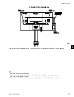
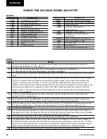


YORK INTERNATIONAL
24
• Pipework and fittings must be separately supported
to prevent any loading on the heat exchanger(s).
Flexible connections are recommended which will
also minimize transmission of vibrations to the
building. Flexible connections must be used if the
unit is mounted on anti-vibration mounts as some
movement of the unit can be expected in normal
operation.
• Pipework and fittings immediately next to the heat
exchangers should be readily de-mountable to en-
able cleaning prior to operation, and to facilitate
visual inspection of the exchanger nozzles.
• Each heat exchanger must be protected by a
strainer, preferably of 40 mesh, fitted as close as
possible to the liquid inlet connection, and provided
with a means of local isolation.
• The heat exchanger(s) must not be exposed to flush-
ing velocities or debris released during flushing. It
is recommended that a suitably sized by-pass and
valve arrangement is installed to allow flushing of
the pipework system. The by-pass can be used dur-
ing maintenance to isolate the heat exchanger with-
out disrupting flow to other units.
• Thermometer and pressure gauge connections
should be provided on the inlet and outlet connec-
tions of each heat exchanger.
• Drain and air vent connections should be provided
at all low and high points in the pipework to per-
mit drainage of the system, and to vent any air in
the pipes.
• Liquid systems at risk of freezing, due to low am-
bient temperatures, should be protected using in-
sulation and heater tape and/or a suitable glycol
solution. The liquid pump(s) must also be used to
ensure liquid is circulated when the ambient tem-
perature approaches freezing point. Insulation
should also be installed around the heat exchanger
nozzles.
Heater tape of 21 watts per meter un-
der the insulation is recommended,
supplied independently and controlled
by an ambient temperature thermostat
set to switch on at 3°C above the freez-
ing temperature of the liquid.
Any debris left in the water pipework
between the strainer and heat ex-
changer could cause serious damage
to the tubes in the heat exchanger and
must be avoided. The installer/user
must also ensure that the quality of
the water in circulation is adequate,
without any dissolved gasses which
can cause oxidation of steel parts
within the heat exchanger(s).
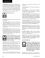
WATER TREATMENT
The unit performance given in the Design Guide is
based on a fouling factor of 0.044 m² °C/kW (0.00025
ft²hr °F/Btu). Dirt, scale, grease and certain types of
water treatment will adversely affect the heat exchanger
surfaces and therefore unit performance. Foreign mat-
ter in the water system(s) can increase the heat ex-
changer pressure drop, reducing the flow rate and caus-
ing potential damage to the heat exchanger tubes.
Aerated, brackish or salt water is not recommended for
use in the water system(s). YORK recommends that a
water treatment specialist is consulted to determine that
the proposed water composition will not affect the
evaporator materials of carbon steel and copper. The
pH value of the water flowing through the heat exchang-
ers must be kept between 7 and 8.5.
Glycol Solutions
For unit operation with chilled liquid temperatures leav-
ing the cooler at below 4.4°C, glycol solutions should
be used to help prevent freezing. Section 9, gives rec-
ommended solution strength with water, as a percent-
age by weight, for the most common types of glycol. It
is important to check glycol concentration regularly to
ensure adequate concentration and avoid possible
freeze-up in the cooler.
When using glycol solutions, pressure
drops are higher than with water. Spe-
cial care must be taken not to exceed
the maximum pressure drop allowed.
Installation
Содержание YCWS0313SC
Страница 12: ...YORK INTERNATIONAL 12 THIS PAGE INTENTIONALLY LEFT BLANK TO MAINTAIN PAGE FORMAT...
Страница 36: ...YORK INTERNATIONAL 36 THIS PAGE INTENTIONALLY LEFT BLANK TO MAINTAIN PAGE FORMAT Commissioning...
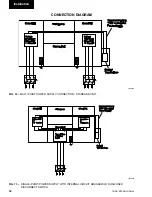
Страница 86: ...YORK INTERNATIONAL 86 TYPICAL CONTROL PANEL WIRING Maintenance...
Страница 87: ...FORM 201 24 NM2 87 YORK INTERNATIONAL TYPICAL CONTROL PANEL WIRING LD06957 8...
Страница 91: ...FORM 201 24 NM2 91 YORK INTERNATIONAL THIS PAGE INTENTIONALLY LEFT BLANK TO MAINTAIN PAGE FORMAT 9...
Страница 101: ...FORM 201 24 NM2 101 YORK INTERNATIONAL SECTION 10 SPARE PARTS This information will be available at a later date 10...
Страница 103: ...FORM 201 24 NM2 103 YORK INTERNATIONAL NOTES 11...