


YORK INTERNATIONAL
40
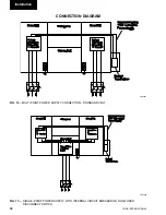
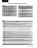
All wiring to the logic section customer terminal blocks
are nominal 30VDC and must be run in screened cable,
with the screen earthed at panel end only. Run screen
cable separately from mains cable to avoid electrical
noise pick-up. Use the gland plate on the back of the
logic section to avoid the mains cables. The length of
the cable must not exceed 7.5 meters.
The voltage free contacts must be suitable for 30VDC
(gold contacts recommended). If voltage free contacts
form part of a relay or contactor, the coil of this device
must be suppressed by using a standard R/C suppres-
sor. The above precautions must be taken to avoid elec-
trical noise which could cause a malfunction or dam-
age to the units and its controls.
The microprocessor based control system can accept
remote signals to start and stop the chiller, to adjust
maximum allowable running current for each compres-
sor, and to adjust the chilled liquid leaving tempera-
ture setpoint. These functions can easily be controlled
by connecting user supplied ‘voltage free’ contacts to
the customer terminals in the control panel.
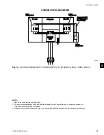
1.11 REMOTE START/STOP
Remote start/stop can be accomplished using a time clock,
manual contact or other ‘voltage free’ contact in series
with the flow switch (Terminals 13 and 24) connected to
terminals in the logic section of the control panel. The
contact must be closed to allow the chiller to run. Any
time the contact opens, the chiller will shutdown and the
‘NO RUN PERM’ message will be displayed.
The flow switch should never be by-
passed. This will cause damage to the
chiller and invalidate the warranty.
For individual system start stop contacts connect flow
switch to terminal 13 to feed the two start stop con-
tacts. Then connect No. 1 system start stop contact to
terminal 24 and No. 2 system start stop contact to ter-
minal 25. With the associated contact open the ‘NO
RUN PERM’ message will be displayed and the asso-
ciated systems will not run.
1.12 REMOTE CURRENT RESET
The maximum allowable running current for each com-
pressor can be adjusted remotely to a lower value us-
ing repeated timed closure of ‘voltage free’ contacts
(Terminals 13 and 26). The duration of the contact clo-
sure will determine the amount of adjustment.
Generally, this input is used for purposes of demand
limit and operates as follows:
Closing the input contact for a defined period of time
allows reset of the % current limit downward.
• Contact closure of 1 - 11 seconds will allow % cur-
rent limiting to be adjusted downward from 105%
by a maximum of 75%, i.e. to a minimum value of
30% FLA.
EMS current limiting operates independently of the
high average current unload. The microprocessor will
always look at the two current limit setpoints and choose
the lower as the controlling value, whenever remote
current limiting is utilized.
• Contact closures of less than 1 second will be ignored.
• A closure of 11 seconds is the maximum allowable
closure and provides a Current Limit reduction
of 75%.
The remote reset current can be calculated as follows:
REMOTE
RESET = 105% FLA - [(CONTACT CLOSED TIME - 1 SEC) X (75% FLA)]
CURRENT
10 SEC
For example, after a 4 second pulse, the offset would
equal:
REMOTE
RESET
=
105% FLA - [(4 sec - 1 sec) x (75% FLA)]
CURRENT
10 sec
REMOTE
RESET
=
105% - 225% FLA sec
CURRENT
10
REMOTE
RESET
=
82.5% FLA
CURRENT
To maintain a given offset, the contact closure signal
must be repeated at not more than 30 minute intervals
but not less than 30 seconds from the end of each PWM
signal. After 30 minutes, if no refresh is provided, the
setpoint will change back to its original value.
Micropanel
Содержание YCWS0313SC
Страница 12: ...YORK INTERNATIONAL 12 THIS PAGE INTENTIONALLY LEFT BLANK TO MAINTAIN PAGE FORMAT...
Страница 36: ...YORK INTERNATIONAL 36 THIS PAGE INTENTIONALLY LEFT BLANK TO MAINTAIN PAGE FORMAT Commissioning...
Страница 86: ...YORK INTERNATIONAL 86 TYPICAL CONTROL PANEL WIRING Maintenance...
Страница 87: ...FORM 201 24 NM2 87 YORK INTERNATIONAL TYPICAL CONTROL PANEL WIRING LD06957 8...
Страница 91: ...FORM 201 24 NM2 91 YORK INTERNATIONAL THIS PAGE INTENTIONALLY LEFT BLANK TO MAINTAIN PAGE FORMAT 9...
Страница 101: ...FORM 201 24 NM2 101 YORK INTERNATIONAL SECTION 10 SPARE PARTS This information will be available at a later date 10...
Страница 103: ...FORM 201 24 NM2 103 YORK INTERNATIONAL NOTES 11...