


YORK INTERNATIONAL
54
Examples of these displays are as follows where # is
the appropriate system number:
Temperatures and pressures are either measured directly
by transducers and sensors, or computed from these
measurements as follows:
Differential oil pressure is the pressure difference be-
tween oil leaving the discharge oil separator and oil
pressure reaching the compressor. It is calculated by
subtracting oil pressure measured after the oil line fil-
ter from discharge pressure (oil in the oil separator is
at discharge pressure). Typically for a clean oil filter
the drop will be 0.1 to 0.7 bar but may reach up to 3
bar.
Saturated discharge and suction temperatures are calcu-
lated by converting measured pressure to temperature.
Slide valve position is calculated based on the number
of loading steps that the microprocessor has sent to the
slide valve solenoid as a current signal.
Slide valve position is approximate and
should be used for reference only.
Under many conditions, it will be fully
loaded between step 60 to 75 and fully
unloaded between step 0 to 40.
Superheats are the difference between the respective
saturated temperature (converted from pressure) and
the actual.
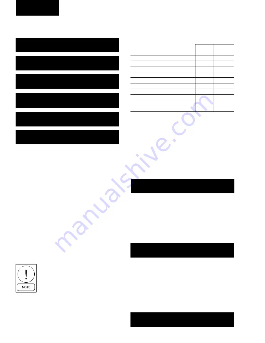
Display limits for the system pressures and tempera-
tures displays are as follows:
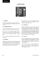
4.4 AMBIENT TEMP KEY
When the key is pressed, ambient air temperature, as
measured surrounding the chiller, is displayed.
Display Limits: Minimum -20.3°C
Maximum 58.8°C
4.5 MOTOR CURRENT KEY
Pressing the key displays compressor current for each
system:
This display shows the average motor current in amps
and average compressor motor current as a percentage
of FLA. All values are approximate.
On the second press of the of the key, the current limit
values as set by the ISN (Remote BAS System) and
EMS-PWM current limiting input are displayed, if they
are active.
S #
S A T
D S C H = 1 3 0 . 0 ° F
D S C H
S H E A T
=
5 4 . 3 ° F
S Y S
#
S
V
S T E P
=
3
S Y S
#
C O O L E R
I N L E T
R E F R I G
T E M P =
2 . 5 ° C
S Y S
#
O I L =
1 . 1
B A R D
S P = 3 . 7 9
D P = 1 7 . 1
B A R G
S Y S
#
O I L
=
5 5 . 5 ° C
S T =
1 . 1
D T =
4 9 . 6 ° C
S #
S A T
S U C T
=
4 . 9 ° C
S U C T
S H E A T
=
1 0 . 4 ° C
A M B I E N T
A I R
T E M P
=
2 2 . 2
° C
C O M P
# = 1 8 6
A M P
1 0 0 % F L A
C O M P
# = 1 3 5
A M P
9 9 % F L A
I S N
C R N T
L I M I T :
N O N E
E M S
C R N T
L I M I T :
N O N E
Micropanel
MINIMUM
MAXIMUM
LIMIT
LIMIT
OIL PRESSURE
0 BAR
14 BAR
SUCTION PRESSURE
0 BAR
14 BAR
DISCHARGE PRESSURE
0 BAR
28 BAR
SUCTION TEMPERATURE*
-13°C
29°C
DISCHARGE TEMPERATURE
5°C
150°C
OIL TEMPERATURE
5°C
116°C
SATURATED DISCHARGE TEMPERATURE
-41°C
60°C
SATURATED SUCTION TEMPERATURE
-41°C
39°C
SLIDE VALVE POSITION
0%
100%
SUCTION SUPERHEAT*
-63°C
16°C
NOTES:
1. *Below 13°C the Suction Temperature display will disappear.
2. This will in turn cause the Suction Superheat display to disap-
pear.
3. Minimum and maximum values may change as software
(EPROM) revisions are made.
TABLE 4 – DISPLAY LIMITS
Содержание YCWS0313SC
Страница 12: ...YORK INTERNATIONAL 12 THIS PAGE INTENTIONALLY LEFT BLANK TO MAINTAIN PAGE FORMAT...
Страница 36: ...YORK INTERNATIONAL 36 THIS PAGE INTENTIONALLY LEFT BLANK TO MAINTAIN PAGE FORMAT Commissioning...
Страница 86: ...YORK INTERNATIONAL 86 TYPICAL CONTROL PANEL WIRING Maintenance...
Страница 87: ...FORM 201 24 NM2 87 YORK INTERNATIONAL TYPICAL CONTROL PANEL WIRING LD06957 8...
Страница 91: ...FORM 201 24 NM2 91 YORK INTERNATIONAL THIS PAGE INTENTIONALLY LEFT BLANK TO MAINTAIN PAGE FORMAT 9...
Страница 101: ...FORM 201 24 NM2 101 YORK INTERNATIONAL SECTION 10 SPARE PARTS This information will be available at a later date 10...
Страница 103: ...FORM 201 24 NM2 103 YORK INTERNATIONAL NOTES 11...