


YORK INTERNATIONAL
28
tomer has master control of the pump, the terminals
must be used to override the customer master start/stop
so that the unit can start the pump in the event of a low
liquid temperature condition.
Common Run Signal (CRS)
Terminals 3 and 4 close to indicate that a system is
running. These terminals may be used to start the cool-
ing liquid pump(s) for the condenser.
System Alarm (SA)
Terminals 1 and 8 (system 1) and 1 and 7 (system 2)
close to indicate an alarm condition whenever a sys-
tem locks out, or there is a power failure.
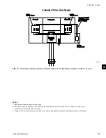
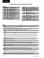
CONTROL PANEL WIRING
All wiring to the control panel terminal block (XTB1)
(nominal 30VDC) must be run in screened cable, with
the screen earthed at the panel end only. Run screened
cable separately from mains cable to avoid electrical
noise pick-up.
The voltage free contacts connected to XTB1 must be
suitable for 30VDC (gold contacts recommended). If the
voltage free contacts form part of a relay or contactor,
the coil of the device must be suppressed using a stan-
dard R/C suppressor. The above precautions must be
taken to avoid electrical noise which could cause a mal-
function or damage to the unit and its controls.
The length of cable to these terminals
must not exceed 7.5 m.
Flow Switch (SF)
A chilled liquid flow switch of suitable type must be
connected to terminals 24 and 13 to provide adequate
protection against loss of liquid flow.
Remote Run/Stop
Connect remote switch(es) in series with the flow
switch to provide remote run/stop control if required.
Remote Print (PNT)
Closure of suitable contacts connected to terminals 28
and 13 will enable a hard copy printout of Operating
Data/Fault History to be obtained (an optional printer
Installation
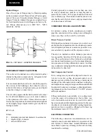
Control Transformer Primary Voltage Tappings
It is important to check that the correct primary tap-
ping has been used on the control transformer:
• With the supply to the unit isolated remove the lid
to the transformer box.
• Check that the tapping used conforms to the site
supply voltage. The two tappings are 342-424V and
360-440V.
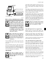
Remote Emergency Stop Device (QRRSB)
A remote emergency stop device may be wired into the
unit. This device should be rated at 8 amps, 230V, AC-
15 and is protected by a maximum fuse size of 8 amps
class gG.
The emergency stop device should be wired into ter-
minals 3 and 4 of the door interlocked emergency stop
device located in the common input section after re-
moving the link.
COMMON INPUT SECTION WIRING
All wiring to the customer relay board (ACRB) volt
free contacts (XVFT) require a supply, maximum 254V,
provided by the customer. The customer must take par-
ticular care deriving the supplies for the volt free ter-
minals with regard to a common point of isolation.
These circuits when used must be fed via the common
point of isolation so that the voltage is removed when
the common point of isolation to the unit is opened.
In accordance with National Electri-
cal Code (N.E.C.) it is recommended
that the customer wiring to these ter-
minals uses orange wires. This will
ensure that circuits not switched off
by the supply disconnecting device are
distinguished by color so that they can
easily be identified as live even when
the disconnecting device is off.
The volt-free contacts are rated at 125VA. All inductive
devices (relays) switched by the volt-free contacts must have
their coil suppressed using standard R/C suppressors.
Chilled Liquid Pump (CLP)
Terminals 5 and 6 (XVFT) close to start the chilled
liquid pump. These terminals can be used as a master
start/stop for the pump in conjunction with the daily
start/stop schedule. If no schedule is set, and the cus-
Содержание YCWS0313SC
Страница 12: ...YORK INTERNATIONAL 12 THIS PAGE INTENTIONALLY LEFT BLANK TO MAINTAIN PAGE FORMAT...
Страница 36: ...YORK INTERNATIONAL 36 THIS PAGE INTENTIONALLY LEFT BLANK TO MAINTAIN PAGE FORMAT Commissioning...
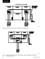
Страница 86: ...YORK INTERNATIONAL 86 TYPICAL CONTROL PANEL WIRING Maintenance...
Страница 87: ...FORM 201 24 NM2 87 YORK INTERNATIONAL TYPICAL CONTROL PANEL WIRING LD06957 8...
Страница 91: ...FORM 201 24 NM2 91 YORK INTERNATIONAL THIS PAGE INTENTIONALLY LEFT BLANK TO MAINTAIN PAGE FORMAT 9...
Страница 101: ...FORM 201 24 NM2 101 YORK INTERNATIONAL SECTION 10 SPARE PARTS This information will be available at a later date 10...
Страница 103: ...FORM 201 24 NM2 103 YORK INTERNATIONAL NOTES 11...