


FORM 201.24-NM2
39
YORK INTERNATIONAL
1.6 CIRCUIT BREAKERS (QCB)
Circuit breakers are provided for the 115VAC controls.
Individual circuit breakers remove the control supply
to each refrigerant circuit. Specifically, the 115VAC
fed to the ARB boards, which energize the contactors
and solenoids.
An additional circuit breaker removes the control sup-
ply to the transformers which feed the APB board FMP
modules and AIOB board.
The circuit breakers remove the
115VAC control supply only. The 3-
phase circuitry will still be energized
from the 400VAC supply.
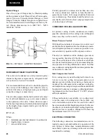
1.7 CURRENT TRANSFORMERS (CT)
Current transformers located internally in the motor pro-
tector modules (one for each of the 3-phases of the power
wiring of each compressor motor) send a VDC signal pro-
portional to motor current to the AIOB. These analogue
levels are then converted to a digital signal and fed to the
AMB board allowing the microprocessor to monitor mo-
tor currents for low current and high current.
1.8 TRANSFORMERS
Transformers are located in the control panel, which
convert the 115VAC control supply to 24VAC to oper-
ate the microprocessor circuitry, 24VAC to operate the
motor protection modules and 12VAC to the AIOB to
drive the slide valves.
1.9 MOTOR PROTECTOR MODULES
A motor protector module for each compressor is lo-
cated in the control panel. These modules provide mo-
tor over-temperature protection, 3-phase current pro-
tection, phase imbalance, phase rotation, and a program-
ming and troubleshooting 7 segment display.
The motor over-temperature protection is supplied by
3 temperature sensors imbedded in the motor windings
120 degrees apart. The module monitors these sensors
allowing it to sense a hot winding and shutdown the
compressor if motor cooling is inadequate.
The onboard CTs provide 3-phase current protection
which look at phase current and send an analogue sig-
nal proportional to average motor current to AIOB
board and on to the AMB board for microprocessor
low/high current protection and current display. This
allows the microprocessor to monitor current and shut
a system down if low or high motor current is sensed.
This is a non-adjustable protection circuit electroni-
cally sized to a system’s motor specifications.
Internally, the onboard 3 CTs and internal circuitry al-
low the motor protector module to protect against high
motor current as programmed on the motor protector
dip switches. These switches are set at the factory ac-
cording to motor specifications.
The module also provides phase rotation protection to
assure the screw compressor does not rotate backwards.
A single phase protection circuit located in the module
also monitors for a phase imbalance. If current imbal-
ance exceeds a number of preset levels of the average
motor current in one of the phases, the motor protector
will recognize it and shutdown the system.
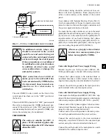
Whenever the Motor Protector Module senses a fault,
an internal contact will open and shutdown the system.
This contact is wired in series with the compressor
motor contactor. When the contact opens, the micro-
processor will attempt to start the system 2 more times.
Since the motor contactor signal path from the ARB
board to the motor contactor is broken by the motor
protector module contact, it will lock the system out
after 3 faults.
The motor protector module must then be reset by re-
moving 115VAC power from the control panel. After
the motor protector is reset, the individual system switch
must be switched ‘OFF’ and then ‘ON’ to reset the
microprocessor to allow restart of the system.
When a module faults, a thorough in-
vestigation of the problem should be
performed before attempting to return
the system to operation. Failure to
perform this investigation could lead
to motor or compressor failure.
1.10 LOGIC SECTION
The logic section of the control panel
contains the relay output boards
(ARB), which have 115VAC connected
to them.
7
Содержание YCWS0313SC
Страница 12: ...YORK INTERNATIONAL 12 THIS PAGE INTENTIONALLY LEFT BLANK TO MAINTAIN PAGE FORMAT...
Страница 36: ...YORK INTERNATIONAL 36 THIS PAGE INTENTIONALLY LEFT BLANK TO MAINTAIN PAGE FORMAT Commissioning...
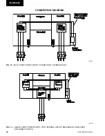
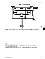
Страница 86: ...YORK INTERNATIONAL 86 TYPICAL CONTROL PANEL WIRING Maintenance...
Страница 87: ...FORM 201 24 NM2 87 YORK INTERNATIONAL TYPICAL CONTROL PANEL WIRING LD06957 8...
Страница 91: ...FORM 201 24 NM2 91 YORK INTERNATIONAL THIS PAGE INTENTIONALLY LEFT BLANK TO MAINTAIN PAGE FORMAT 9...
Страница 101: ...FORM 201 24 NM2 101 YORK INTERNATIONAL SECTION 10 SPARE PARTS This information will be available at a later date 10...
Страница 103: ...FORM 201 24 NM2 103 YORK INTERNATIONAL NOTES 11...