


FORM 201.24-NM2
53
YORK INTERNATIONAL
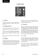
4.1 GENERAL
The display keys provide direct access to retrieve com-
monly required data about the operation of the chiller.
This is particularly useful during commissioning, moni-
toring the operation of the chiller, diagnosing potential
future problems and service troubleshooting.
When a display key is pressed, the corresponding mes-
sage will be displayed and will remain on the display
until another key is pressed.
Displayed data is in ‘real-time’ and is updated approxi-
mately every 2 seconds. If updating of one of the mes-
sages is required faster than every 2 seconds, the ap-
propriate key for the desired display can be pushed and
held to provide updating every 0.4 seconds.
Display messages may show characters indicating
‘greater than’ (>) or ‘less than’ (<). These characters
indicate the actual values are greater than or less than
the values which are being displayed, but are outside
the ability of the microprocessor to give an actual read-
ing. This is unlikely to occur unless a problem exists in
the measuring sensors or during extreme conditions.
The display keys and the data available from each is as
follows:
4.2 CHILLED LIQUID TEMPS KEY
When the key is pressed the chiller leaving chilled liq-
uid temperature (LCHLT) and returning chilled liquid
temperature (RCHLT) are displayed.
If the key is pressed again, the following message will
appear if the leaving hot liquid temperature sensor is
fitted on units with a water cooled condenser. If a sensor
is not installed, pressing the key will have no effect.
4.3 SYSTEM DATA KEYS
Repeatedly pressing one of the ‘SYSTEM # DATA’
keys scrolls through displays of:
• Differential oil pressure (OIL)
• Suction pressure (SP)
• Discharge pressure (DP)
• Oil temperature
• Suction temperature (ST)
• Discharge temperature (DT)
• Saturated suction temperature
• Suction superheat
• Saturated discharge temperature
• Discharge superheat
• Compressor slide valve position
• Cooler inlet refrigerant temperature
29023a
4. DISPLAY KEYS
L C H L T
=
9 . 5
°
C
R C H L T
=
1 1 . 0
°
C
L
H L T
=
2 9 . 0
°
C
7
Содержание YCWS0313SC
Страница 12: ...YORK INTERNATIONAL 12 THIS PAGE INTENTIONALLY LEFT BLANK TO MAINTAIN PAGE FORMAT...
Страница 36: ...YORK INTERNATIONAL 36 THIS PAGE INTENTIONALLY LEFT BLANK TO MAINTAIN PAGE FORMAT Commissioning...
Страница 86: ...YORK INTERNATIONAL 86 TYPICAL CONTROL PANEL WIRING Maintenance...
Страница 87: ...FORM 201 24 NM2 87 YORK INTERNATIONAL TYPICAL CONTROL PANEL WIRING LD06957 8...
Страница 91: ...FORM 201 24 NM2 91 YORK INTERNATIONAL THIS PAGE INTENTIONALLY LEFT BLANK TO MAINTAIN PAGE FORMAT 9...
Страница 101: ...FORM 201 24 NM2 101 YORK INTERNATIONAL SECTION 10 SPARE PARTS This information will be available at a later date 10...
Страница 103: ...FORM 201 24 NM2 103 YORK INTERNATIONAL NOTES 11...