


YORK INTERNATIONAL
34
Switch Settings: Ensure that the unit ‘ON/OFF’ toggle
switch on the control panel and the microprocessor
board system switches ‘S2’ and ‘S3’ are set to ‘OFF’.
Set the red emergency stop device on the common in-
put section to ‘1’ (ON). For units fitted with door in-
terlocked isolators the power section doors must be
closed and the devices set to ‘1’ (ON). The customers
disconnection devices can now be set to ‘ON’.
The unit is now live!
Compressor heaters: Verify the compressor heaters
are energized.
Chilled Liquid System: Verify that the chilled liquid
system has been installed correctly, and has been com-
missioned with the correct direction of water flow
through the cooler. Purge air from the top of the cooler
using the plugged air vent mounted on the top of the
cooler body.
Cooling Liquid System: Verify that the cooling liq-
uid system has been installed correctly, and has been
commissioned with the correct direction of water flow
through the condenser. Purge air from the top of the
condenser using the plugged air vent mounted at the
top of the condenser water head.
Cooler and Condenser flow rates and
pressure drops must be within the lim-
its given in Section 9. Operation out-
side of these limits is undesirable and
could cause damage.
Flow switch: Verify a chilled liquid flow switch is cor-
rectly fitted in the customer’s pipework on the cooler
outlet, and wired into the control panel correctly.
Temperature sensor(s): Ensure the chilled liquid tem-
perature sensors are coated with heat conductive com-
pound (Part No. 013-00890-000) and inserted in the
sensor pockets of the cooler. This outlet sensor also
acts as the freeze protection thermostat sensor and must
always be fitted.
Ensure the cooling liquid temperature sensor is coated
with heat conductive compound (Part No. 013-00890-
000) and inserted in the outlet sensor pocket of the
condenser.
Control supply: Verify the control panel display is
illuminated.
HP Cutout Reset: Check that the hand reset mechani-
cal high pressure cutouts mounted on the compressors
are at the correct setting and are reset.
Programmed Options: Verify that the options factory
programmed into the Microprocessor Based Control Sys-
tem are in accordance with the customers order require-
ments by pressing the ‘OPTIONS’ key on the keypad and
reading the settings from the display. Refer to the MBCS
Section for notes and explanation of messages.
Programmed Settings: Ensure the system cutout and
operational settings are in accordance with the instruc-
tions given in the MBCS Section and with operational
requirements by pressing the ‘PROGRAM’ key.
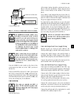
Date and time: Program the date and time by first en-
suring that the CLK jumper J18 on the microprocessor
board is in the ‘ON’ position. Then press the ‘SET
TIME/DATE’ key and set the date and time (see MBCS
Section).
Start/Stop Schedule: Program the daily and holiday
start/stop by pressing the ‘SET SCHEDULE/HOLI-
DAY’ key (see MBCS Section).
Setpoints: Set the required leaving chilled liquid tem-
perature setpoint and control range using the ‘LOCAL
COOLING SETPOINTS’ and ‘REMOTE COOLING
SETPOINTS’ keys. (see MBCS Section).
FIRST TIME START-UP
During the commissioning period
there should be sufficient heat load to
run the unit under stable full load op-
eration to enable the unit controls, and
system operation to be set up correctly
and a commissioning log taken. Read
the following section in conjunction
with the MBCS Section, then proceed
step by step as follows:
Interlocks: Verify that liquid is flowing through the
cooler and that heat load is present. Ensure that any re-
Commissioning
Содержание YCWS0313SC
Страница 12: ...YORK INTERNATIONAL 12 THIS PAGE INTENTIONALLY LEFT BLANK TO MAINTAIN PAGE FORMAT...
Страница 36: ...YORK INTERNATIONAL 36 THIS PAGE INTENTIONALLY LEFT BLANK TO MAINTAIN PAGE FORMAT Commissioning...
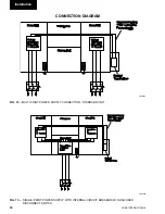
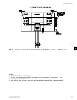
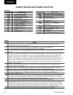
Страница 86: ...YORK INTERNATIONAL 86 TYPICAL CONTROL PANEL WIRING Maintenance...
Страница 87: ...FORM 201 24 NM2 87 YORK INTERNATIONAL TYPICAL CONTROL PANEL WIRING LD06957 8...
Страница 91: ...FORM 201 24 NM2 91 YORK INTERNATIONAL THIS PAGE INTENTIONALLY LEFT BLANK TO MAINTAIN PAGE FORMAT 9...
Страница 101: ...FORM 201 24 NM2 101 YORK INTERNATIONAL SECTION 10 SPARE PARTS This information will be available at a later date 10...
Страница 103: ...FORM 201 24 NM2 103 YORK INTERNATIONAL NOTES 11...