215
JOHNSON CONTROLS
FORM 201.21-NM3 (616)
OPTIONAL HIGH IPLV CAPACITY CONTROL
(Loading/Unloading and starting additional compressors)
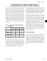
Optional “High IPLV” Capacity Control is installed
in the chiller at the factory using a dedicated EPROM
(software), part # 031-02476-002, for “High” IPLV
control. It’s purpose is to control compressors as ef-
fectively as possible, optimizing control of both the
compressors and condenser fans. If the LWT is > the
programmed Se CR, the Chiller Control Board
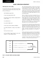
microprocessor will follow the flow chart (Page 209)
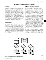
to determine the number of compressors to start based
on the last run time, time off, and the rate of change
of chilled liquid temperature. The compressor(s) will
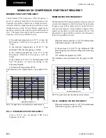
start at the minimum start frequency based on ambient
temperature (Page 210). The respective system Feed and
Drain Valves will immediately begin to control superheat
and liquid level in the Flash Tank.
When compressors start, the load and unload timers
will be set to 30 seconds. During the first 30 seconds of
operation after a compressor reaches the start frequency,
loading/unloading is inhibited. After 30 seconds, the
control logic looks at the LWT temp, compares it to
the Setpoint plus CR, and makes a decision to load or
unload.
For precise capacity control, the Chiller Control Board
microprocessor loads and unloads compressors quickly,
as fast as every 2 seconds, in increments of 0.1-1 Hz each
time a load or unload change is required. Fixed load and
unload timers of 2 sec. are set, after a speed change of
0.1-1 Hz, to minimize undershoot and overshoot.
As additional cooling is required (LCHLT > Setpoint
+ CR), the Chiller Control Board microprocessor will
increase the speed of the compressor at the rate of 1Hz
every 2 seconds until the load is satisfied. Loading
will continue to occur as long as leaving chilled liquid
temperature is above the Se CR.
The chiller control board will be make decisions regard-
ing speed changes under conditions where the “error”
and “rate” conflict. Under these conditions, loading/un
-
loading follows the guidelines described in the Fuzzy
Logic Control Section (Page 216).
If chilled liquid temperature is not satisfied and above
Se CR, the microprocessor looks to see if
any of the lag compressors are not running. If any
lag compressor(s) is off, the Chiller Control Board
microprocessor looks at the VSD output frequency.
If the VSD output frequency is greater than the ADD
COMPRESSOR FRE 15 Hz or equal to
the maximum chiller speed (frequency), the micro-
processor starts an additional compressor. The ADD
COMPRESSOR FREQUENCY is calculated as:
For example: A single compressor had been running
ADD = Minimum Start Freq x (Number of Compressors R1)
COMPRESSOR
Number of Compressors Running
FREQUENCY
without satisfying cooling demands. Assume the mini-
mum VSD start frequency based on ambient is 50 Hz
for this example. The number of compressors running
in the formula will equal to 1. Placing the values into
the formula: 50 Hz x (1+1)/1 = 100 Hz. The add com-
pressor frequency will equal 100 Hz. Since the controls
are designed to add a compressor at a frequency 15 Hz
above this point, a compressor will be added if the speed
reaches 115 Hz.
When a compressor is to be added, the Chiller Control
Board microprocessor decelerates the compressor VSD
frequency to 5 Hertz. This enables the differential
between discharge and suction pressure to be reduced
to a point where it will not affect motor current when
the compressor is restarted. It also reduces the chance
for backspin on the running compressor. The next lag
compressor is activated and all compressors are ac-
celerated to the START FREQUENCY. The START
FREQUENCY is calculated as:
START
= Current VSD Freq x (Number of Compressors Running –1)
FREQUENCY
Number of Compressors Running
7
Содержание YCAV0267E
Страница 61: ...61 JOHNSON CONTROLS FORM 201 21 NM3 616 This intentionally left blank 6 ...
Страница 63: ...63 JOHNSON CONTROLS FORM 201 21 NM3 616 ELEMENTARY CONTROL WIRING DIAGRAM 3 COMPRESSOR CON T LD12552 ...
Страница 67: ...67 JOHNSON CONTROLS FORM 201 21 NM3 616 LD12556 POWER ELEMENTARY DIAGRAM 3 COMPRESSOR YCAV CHILLER CON T 6 ...
Страница 72: ...72 JOHNSON CONTROLS FORM 201 21 NM3 616 035 20326 006 REV TECHNICAL DATA LD11125 LOCATION LABEL ...
Страница 73: ...73 JOHNSON CONTROLS FORM 201 21 NM3 616 This page intentionally left blank 6 ...
Страница 88: ...88 JOHNSON CONTROLS FORM 201 21 NM3 616 LOCATION LABEL TECHNICAL DATA 035 20890 008 REV LD11140 ...
Страница 89: ...89 JOHNSON CONTROLS FORM 201 21 NM3 616 6 035 20890 009 REV LOCATION LABEL CON T LD11141 ...
Страница 146: ...146 JOHNSON CONTROLS FORM 201 21 NM3 616 TECHNICAL DATA This page intentionally left blank ...
Страница 147: ...147 JOHNSON CONTROLS FORM 201 21 NM3 616 6 This page intentionally left blank ...
Страница 247: ...247 JOHNSON CONTROLS FORM 201 21 NM3 616 This page intentionally left blank ...
Страница 269: ...269 JOHNSON CONTROLS FORM 201 21 NM3 616 This page intentionally left blank 8 ...
Страница 289: ...289 JOHNSON CONTROLS FORM 201 21 NM3 616 8 This page intentionally left blank ...
Страница 317: ...317 JOHNSON CONTROLS FORM 201 21 NM3 616 8 This page intentionally left blank ...
Страница 348: ...348 JOHNSON CONTROLS FORM 201 21 NM3 616 MAINTENANCE NOTES ...
Страница 349: ...349 JOHNSON CONTROLS FORM 201 21 NM3 616 9 NOTES ...


