


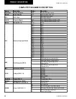
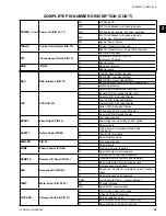
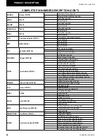
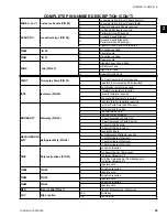


27
JOHNSON CONTROLS
FORM 201.21-NM3 (616)
3
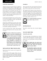
MOVING THE CHILLER
Prior to moving the unit, ensure that the installation
site is suitable for installing the unit and is easily ca-
pable of supporting the weight of the unit and all as-
sociated services.
The unit must only be lifted by the base
frame at the points provided. Never move
the unit on rollers, or lift the unit using a
forklift truck.
Care should be taken to avoid damaging the condenser
cooling fins when moving the unit.
UNIT REMOVAL FROM SHIPPING
CONTAINER
1. Place a clevis pin into the holes provided at the
end of each base rail on the unit. Attach chains or
nylon straps through the clevis pins and hook onto
a suitable lift truck for pulling the unit out of the
container.
2. Slowly place tension on the chains or straps until
the unit begins to move and then slowly pull the
unit from the container. Be sure to pull straight so
the sides do not scrape the container.
3.
Place a lifting fixture on the forks of the lift truck
and reattach the chain or strap. Slightly lift the
front of the unit to remove some weight from the
floor of the container. Continue pulling the unit
with an operator on each side to guide the lift
truck operator.
4. Pull the unit until the lifting locations are outside
of the container. Place 4 X 4 blocks of wood under
the base rails of the unit. Gently rest the unit on
the blocks and remove the chains and lift truck.
5. Attach lifting rigging from the crane and slowly
complete the removal from the container then lift
up and away.
LD19197a
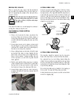
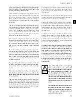
LIFTING USING LUGS
Units are provided with lifting holes in the base frame
which accept the accessory lifting lug set as shown in
the figure below. The lugs (RH and LH) should be in-
serted into the respective holes in the base frame and
turned so that the spring loaded pin engages into the
hole and the flanges on the lug lock behind the hole.
The lugs should be attached to the cables/chains using
shackles or safety hooks.
LOCKING PIN
LUG
FLANGE
LIFTING HOLE
IN BASE FRAME
CORRECT
LOCKING PIN
LUG
LIFTING HOLE
IN BASE FRAME
FLANGE
INCORRECT
LOCKING
PIN
FLANGE
LUG
LD19197b
LIFTING USING SHACKLES
The shackles should be inserted into the respective
holes in the base frame and secured from the inside.
Use spreader bars to avoid lifting chains hitting the
chiller. Various methods of spreader bar arrangements
may be used, keeping in mind the intent is to keep the
unit stable and to keep the chains from hitting the chill-
er and causing damage.
Never lift the chiller using a forklift or by hooking to
the top rails. Use only the lifting holes provided.
Lifting Instructions are placed on a label on the chiller
and on the shipping bag.
Содержание YCAV0267E
Страница 61: ...61 JOHNSON CONTROLS FORM 201 21 NM3 616 This intentionally left blank 6 ...
Страница 63: ...63 JOHNSON CONTROLS FORM 201 21 NM3 616 ELEMENTARY CONTROL WIRING DIAGRAM 3 COMPRESSOR CON T LD12552 ...
Страница 67: ...67 JOHNSON CONTROLS FORM 201 21 NM3 616 LD12556 POWER ELEMENTARY DIAGRAM 3 COMPRESSOR YCAV CHILLER CON T 6 ...
Страница 72: ...72 JOHNSON CONTROLS FORM 201 21 NM3 616 035 20326 006 REV TECHNICAL DATA LD11125 LOCATION LABEL ...
Страница 73: ...73 JOHNSON CONTROLS FORM 201 21 NM3 616 This page intentionally left blank 6 ...
Страница 88: ...88 JOHNSON CONTROLS FORM 201 21 NM3 616 LOCATION LABEL TECHNICAL DATA 035 20890 008 REV LD11140 ...
Страница 89: ...89 JOHNSON CONTROLS FORM 201 21 NM3 616 6 035 20890 009 REV LOCATION LABEL CON T LD11141 ...
Страница 146: ...146 JOHNSON CONTROLS FORM 201 21 NM3 616 TECHNICAL DATA This page intentionally left blank ...
Страница 147: ...147 JOHNSON CONTROLS FORM 201 21 NM3 616 6 This page intentionally left blank ...
Страница 247: ...247 JOHNSON CONTROLS FORM 201 21 NM3 616 This page intentionally left blank ...
Страница 269: ...269 JOHNSON CONTROLS FORM 201 21 NM3 616 This page intentionally left blank 8 ...
Страница 289: ...289 JOHNSON CONTROLS FORM 201 21 NM3 616 8 This page intentionally left blank ...
Страница 317: ...317 JOHNSON CONTROLS FORM 201 21 NM3 616 8 This page intentionally left blank ...
Страница 348: ...348 JOHNSON CONTROLS FORM 201 21 NM3 616 MAINTENANCE NOTES ...
Страница 349: ...349 JOHNSON CONTROLS FORM 201 21 NM3 616 9 NOTES ...