200
JOHNSON CONTROLS
FORM 201.21-NM3 (616)
TECHNICAL DATA
CHILLER ELECTRONIC COMPONENTS (CON'T)
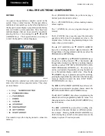
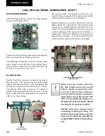
VSD LOGIC BOARD
The VSD Logic Board controls VSD functions/
operations and communicates through a serial commu-
nications line with the Chiller Control Board. Safety
and shutdown information stored in the RTC (Battery
backed RAM) is reported back to the Chiller Control
Board via the communications link. The VSD Logic
Board converts the speed and run commands from the
Chiller Control Board into the necessary voltage and
frequency commands to operate the inverter section.
The VSD Logic Board also controls the converter
section of the VSD (AC to DC conversion) by
controlling the pre-charge function.
The VSD Logic Board contains a second microprocessor
for motor control, which generates the PWM signals that
control the IGBT’s in the inverter section of the VSD.
The VSD Logic Board contains an FPGA
(Field Programmable Gate Array) which handles the
hardware safeties and can shut down the VSD much
faster than the software safeties, since they are not
dependent upon running program loops in software. The
VSD handles all VSD related safeties including high
motor current, overload, DC bus voltage faults, etc.
Inputs to the VSD Logic Board are fed through an
onboard multiplexer (MUX) before being sent to the A/D
converter. These signals allow the VSD Logic Board to
monitor DC Bus voltages, compressor motor currents,
VSD internal ambient temperature, IGBT baseplate
temperatures, and compressor overload settings.
LD10615
RTC
The VSD Logic Board controls the glycol pump and
the cabinet cooling fans. Details on the controls are
provided in the VSD Operation and Control section,
Page 234.
CONTROL PANEL TO VSD
COMMUNICATIONS
Communication between the VSD Logic Board and the
Chiller Control Board is made via a three-wire RS-485
opto-coupled data link. Communications between the
two boards occurs at the rate of 9600 baud. UART2 of the
dual UART located on the Chiller Control Board is dedi-
cated to internal communications and has a higher prior-
ity interrupt than the external communications UART1.
The Chiller Control Board will control VSD start/stop,
selection of which compressors to run, and compres-
sor speed. The VSD Logic Board will run the desired
compressors at the speed requested by the Chiller
Control Board. The VSD will report back to the Chiller
Control Board, shutdown and safety information related
to internal VSD operation and the compressor motors.
On power-up, the control panel will attempt to initialize
communications with the VSD. The Chiller Control
Board will request initialization data from the VSD
Logic Board. The initialization data required is the
number of compressors and the VSD software version.
Once these data points have been received by the control
panel, the unit has successfully initialized and will not
request them again.
If the Chiller Control Board does not receive
initialization data from the VSD Logic Board in
8 seconds or loses communications with the VSD
for 8 seconds at any time, the chiller will fault on a
communications failure. The Chiller Control Board will
continue to send messages to the VSD Logic Board in
an attempt to establish communications while the chiller
is faulted.
The VSD Logic Board will also monitor a
communications loss. If the VSD Logic Board loses
communications with the Chiller Microprocessor Board
for 8 seconds at any time, the VSD will shut off all
compressors and wait for valid comms from the Chiller
Control Board.
Содержание YCAV0267E
Страница 61: ...61 JOHNSON CONTROLS FORM 201 21 NM3 616 This intentionally left blank 6 ...
Страница 63: ...63 JOHNSON CONTROLS FORM 201 21 NM3 616 ELEMENTARY CONTROL WIRING DIAGRAM 3 COMPRESSOR CON T LD12552 ...
Страница 67: ...67 JOHNSON CONTROLS FORM 201 21 NM3 616 LD12556 POWER ELEMENTARY DIAGRAM 3 COMPRESSOR YCAV CHILLER CON T 6 ...
Страница 72: ...72 JOHNSON CONTROLS FORM 201 21 NM3 616 035 20326 006 REV TECHNICAL DATA LD11125 LOCATION LABEL ...
Страница 73: ...73 JOHNSON CONTROLS FORM 201 21 NM3 616 This page intentionally left blank 6 ...
Страница 88: ...88 JOHNSON CONTROLS FORM 201 21 NM3 616 LOCATION LABEL TECHNICAL DATA 035 20890 008 REV LD11140 ...
Страница 89: ...89 JOHNSON CONTROLS FORM 201 21 NM3 616 6 035 20890 009 REV LOCATION LABEL CON T LD11141 ...
Страница 146: ...146 JOHNSON CONTROLS FORM 201 21 NM3 616 TECHNICAL DATA This page intentionally left blank ...
Страница 147: ...147 JOHNSON CONTROLS FORM 201 21 NM3 616 6 This page intentionally left blank ...
Страница 247: ...247 JOHNSON CONTROLS FORM 201 21 NM3 616 This page intentionally left blank ...
Страница 269: ...269 JOHNSON CONTROLS FORM 201 21 NM3 616 This page intentionally left blank 8 ...
Страница 289: ...289 JOHNSON CONTROLS FORM 201 21 NM3 616 8 This page intentionally left blank ...
Страница 317: ...317 JOHNSON CONTROLS FORM 201 21 NM3 616 8 This page intentionally left blank ...
Страница 348: ...348 JOHNSON CONTROLS FORM 201 21 NM3 616 MAINTENANCE NOTES ...
Страница 349: ...349 JOHNSON CONTROLS FORM 201 21 NM3 616 9 NOTES ...

