


32
JOHNSON CONTROLS
FORM 201.21-NM3 (616)
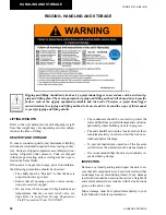
INSTALLATION
WATER TREATMENT
The unit performance provided in the Design Guide
is based on a fouling factor of 0.0001 ft
2
hr°F/Btu
(0.018m2/hr °C/kW). Dirt, scale, grease and certain
types of water treatment will adversely affect the heat
exchanger surfaces and therefore the unit performance.
Foreign matter in the water system(s) can increase the
heat exchanger pressure drop, reducing the flow rate and
causing potential damage to the heat exchanger tubes.
Aerated, brackish or salt water is not recommended
for use in the water system(s). YORK recommends
that a water treatment specialist should be consulted
to determine whether the proposed water composition
will adversely affect the evaporator materials of carbon
steel and copper. The pH value of the water flowing
through the evaporator must be kept in a range between
7 and 8.5.
PIPEWORK ARRANGEMENT
The following is a suggested piping arrangement for
single unit installations. For multiple unit installations,
each unit should be piped as shown in FIG. 3.
-Isolating Valve - Normally Open
-Isolating Valve - Normally Closed
-Flow Regulating Valve
-Flow Measurement Device
-Strainer
-Pressure Tapping
-Flow Switch
-Flanged Connection
-Pipework
FIG. 3 - PIPEWORK ARRANGEMENT
CONNECTION TYPES & SIZES
For connection sizes relevant to individual models refer
to the Technical Data Section.
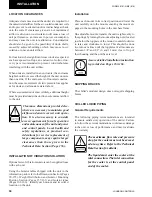
COOLER CONNECTIONS
Standard chilled liquid connections on all coolers are of
the Victaulic Groove type (See FIG. 4).
FIG. 4 - VICTAULIC GROOVE
LD10494
Option Flanges
One of two types of flanges may be fitted depending
on the customer or local Pressure Vessel Code require-
ments. These are Victaulic-Adapter flanges, normally
supplied loose, or weld flanges, which may be supplied
loose or ready-fitted. Victaulic-Adapter and weld flange
dimensions are to ISO 7005 - NP10.
FIG. 5 - FLANGE ATTACHMENT
LD10495
WELD FLANGE
VICTAULIC ADAPTER
LD10507
Содержание YCAV0267E
Страница 61: ...61 JOHNSON CONTROLS FORM 201 21 NM3 616 This intentionally left blank 6 ...
Страница 63: ...63 JOHNSON CONTROLS FORM 201 21 NM3 616 ELEMENTARY CONTROL WIRING DIAGRAM 3 COMPRESSOR CON T LD12552 ...
Страница 67: ...67 JOHNSON CONTROLS FORM 201 21 NM3 616 LD12556 POWER ELEMENTARY DIAGRAM 3 COMPRESSOR YCAV CHILLER CON T 6 ...
Страница 72: ...72 JOHNSON CONTROLS FORM 201 21 NM3 616 035 20326 006 REV TECHNICAL DATA LD11125 LOCATION LABEL ...
Страница 73: ...73 JOHNSON CONTROLS FORM 201 21 NM3 616 This page intentionally left blank 6 ...
Страница 88: ...88 JOHNSON CONTROLS FORM 201 21 NM3 616 LOCATION LABEL TECHNICAL DATA 035 20890 008 REV LD11140 ...
Страница 89: ...89 JOHNSON CONTROLS FORM 201 21 NM3 616 6 035 20890 009 REV LOCATION LABEL CON T LD11141 ...
Страница 146: ...146 JOHNSON CONTROLS FORM 201 21 NM3 616 TECHNICAL DATA This page intentionally left blank ...
Страница 147: ...147 JOHNSON CONTROLS FORM 201 21 NM3 616 6 This page intentionally left blank ...
Страница 247: ...247 JOHNSON CONTROLS FORM 201 21 NM3 616 This page intentionally left blank ...
Страница 269: ...269 JOHNSON CONTROLS FORM 201 21 NM3 616 This page intentionally left blank 8 ...
Страница 289: ...289 JOHNSON CONTROLS FORM 201 21 NM3 616 8 This page intentionally left blank ...
Страница 317: ...317 JOHNSON CONTROLS FORM 201 21 NM3 616 8 This page intentionally left blank ...
Страница 348: ...348 JOHNSON CONTROLS FORM 201 21 NM3 616 MAINTENANCE NOTES ...
Страница 349: ...349 JOHNSON CONTROLS FORM 201 21 NM3 616 9 NOTES ...