332
JOHNSON CONTROLS
FORM 201.21-NM3 (616)
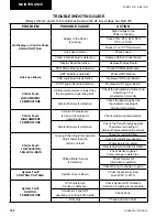
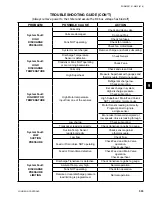
TROUBLESHOOTING GUIDE
PROBLEM
POSSIBLE CAUSE
ACTION
No Display on Control Panel.
Unit will NOT Run.
Supply to the Panel
is missing.
High Voltage to the
Chiller is missing.
Check 1FU, 2FU, 4FU, 5FU
17FU, or 19FU.
Check 2T or 10T Transformer.
Line Fuse is blown.
Check Fuses.
Chiller Control board is defective.
Replace Chiller Control board
Display Board defective.
Replace Display Board
Line Fuse Blows.
SCR Diode Module is defective.
Check SCR/Diode Module.
IGBT Module is defective.
Check IGBT Module.
VSD Logic Board is defective.
Replace VSD Logic Board.
SCR Trigger Board is defective
Replace SCR Trigger Board.
Chiller Fault:
LOW AMBIENT
TEMPERATURE
Ambient temperature is lower than
the programmed operating limit.
Check the programmed cutout and
determine if it is
programmed correctly
Ambient Sensor is defective.
Check the panel against the
thermometer reading of
ambient temperature
Chiller Fault:
HIGH AMBIENT
TEMPERATURE
Ambient Temperature
is above the maximum
operating limit.
Check outside air temperature.
Ambient Sensor is defective.
Check the Panel Display against
Thermometer reading of
Ambient Temperature at the sensor.
Chiller Fault:
LOW LEAVING
CHILLED LIQUID
Leaving chilled liquid temperature
drops faster than the
unit can unload.
Check for restricted flow.
Check for rapid flow changes.
Water loop is too small.
Flow is below minimum for chiller.
Chilled Water Sensor
is defective.
Check Sensor against
Temp. Gauge in water line.
Check Sensor for
intermittent operation.
Check Wiring for shorts or opens.
System Fault:
CONTROL VOLTAGE
System Fuse is blown.
Check respective system
Fuse 20FU or 21FU.
System Fault:
HIGH OIL
TEMPERATURE
Oil Temperature
Sensor is defective.
Check Sensor with infrared to
determine if reading is reasonable.
Condensor Fans NOT
operating or running backwards.
Check Fans.
Coils dirty.
Check and clean Coils.
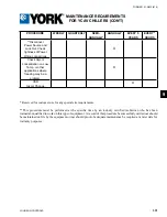
MAINTENANCE
(Always remove power to the chiller and assure the DC bus voltage has bled off)
Содержание YCAV0267E
Страница 61: ...61 JOHNSON CONTROLS FORM 201 21 NM3 616 This intentionally left blank 6 ...
Страница 63: ...63 JOHNSON CONTROLS FORM 201 21 NM3 616 ELEMENTARY CONTROL WIRING DIAGRAM 3 COMPRESSOR CON T LD12552 ...
Страница 67: ...67 JOHNSON CONTROLS FORM 201 21 NM3 616 LD12556 POWER ELEMENTARY DIAGRAM 3 COMPRESSOR YCAV CHILLER CON T 6 ...
Страница 72: ...72 JOHNSON CONTROLS FORM 201 21 NM3 616 035 20326 006 REV TECHNICAL DATA LD11125 LOCATION LABEL ...
Страница 73: ...73 JOHNSON CONTROLS FORM 201 21 NM3 616 This page intentionally left blank 6 ...
Страница 88: ...88 JOHNSON CONTROLS FORM 201 21 NM3 616 LOCATION LABEL TECHNICAL DATA 035 20890 008 REV LD11140 ...
Страница 89: ...89 JOHNSON CONTROLS FORM 201 21 NM3 616 6 035 20890 009 REV LOCATION LABEL CON T LD11141 ...
Страница 146: ...146 JOHNSON CONTROLS FORM 201 21 NM3 616 TECHNICAL DATA This page intentionally left blank ...
Страница 147: ...147 JOHNSON CONTROLS FORM 201 21 NM3 616 6 This page intentionally left blank ...
Страница 247: ...247 JOHNSON CONTROLS FORM 201 21 NM3 616 This page intentionally left blank ...
Страница 269: ...269 JOHNSON CONTROLS FORM 201 21 NM3 616 This page intentionally left blank 8 ...
Страница 289: ...289 JOHNSON CONTROLS FORM 201 21 NM3 616 8 This page intentionally left blank ...
Страница 317: ...317 JOHNSON CONTROLS FORM 201 21 NM3 616 8 This page intentionally left blank ...
Страница 348: ...348 JOHNSON CONTROLS FORM 201 21 NM3 616 MAINTENANCE NOTES ...
Страница 349: ...349 JOHNSON CONTROLS FORM 201 21 NM3 616 9 NOTES ...


