222
JOHNSON CONTROLS
FORM 201.21-NM3 (616)
The Drain Valve, Controller, and Chiller Control Board
Algorithm combination functions as an Electronic
Expansion Valve (EEV). The controller receives an
analog 0-10.28VDC signal sent from the Chiller Control
Board, which is based on system suction pressure and
suction temperature. These operating parameters are
used to compute and control suction superheat accord-
ing to the Setpoint programmed into the panel under
the PROGRAM Key. After computing the superheat,
the signal to the controller is adjusted and the controller
subsequently positions the Drain Valve to control the
superheat. The gain of the control algorithm is adjusted
to aid in correcting for superheat error.
The Chiller Control Board Algorithm assures the level
in the flash tank does not become too high. The level
setpoint for control is 35%. Levels normally run 30-40%
with the economizer solenoid energized (open). With
the solenoid closed, levels may vary significantly from
the 30-40% level. If the level exceeds 85% of the full
level, the system will shut down on a fault.
The Feed and Drain Valves in a system open and begin
to control as soon as a compressor starts. When the
compressor shuts down, the valves are driven to their
closed position.
MOP Setpoint Control For Hot Water Starts
Maximum Operating Pressure control overrides super-
heat control of the Drain Valve when the MOP Setpoint
is exceeded on hot water starts. The fixed setpoint is
68°F Saturated Suction Temp (SST). When this value
is exceeded, the Drain Valve switches superheat control
to suction pressure control equal to 68°F SST.
Moderate To High Ambient MOP
Setpoint Control.
In moderate to high ambients, the suction line may be
warmed by the ambient, contributing to inaccurate suc-
tion superheat measurement at start-up. To avoid this
situation, the MOP control utilizes suction pressure
control at start-up, which overrides superheat control.
For the first minute of run time, the MOP Setpoint is
set to:
RCHLT - Superheat Setpoint – 1.0°F
Run Time in Seconds
FLASH TANK DRAIN AND FEED VALVE CONTROLLER
After the first minute of operation, the MOP Setpoint is
ramped from the current calculated value to 68°F over
the next minute. At this point, normal superheat control
based on the programmed setpoint resumes.
Low Ambient MOP Setpoint Control
In low ambient start-ups, suction pressure is erratic and
pressure differentials across the compressor may be
low, resulting in low oil differential faults. The Low
Ambient MOP setpoint control assures adequate
differential is developed between discharge and
suction to push oil through the oil cooling system and
the compressor.
For the first 5 minutes of system run time, the MOP
Setpoint is set to the saturated suction temperature equal
to 15PSIG below discharge pressure, which overrides
superheat control. The control algorithm will not allow
suction pressure control below the cutout. The low
limit of the suction pressure is the low suction pressure
cutout. After 5 minutes of system run time, the MOP
Setpoint is set at 68°F and superheat control based on
the programmed setpoint resumes.
Actual MOP Setpoint
The actual MOP Setpoint used by the controller is the
minimum of three calculations; the fixed MOP Setpoint,
the moderate to high ambient setpoint, and the low
ambient setpoint.
Valve Controller LED’s
Each Drain and Feed Valve stepper motor controller is
equipped with a pair of LED’s on the left side of the mod-
ule and 10 LED’s in the center of the module (FIG. 39).
These LED’s may be useful during troubleshooting.
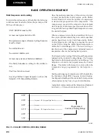
FIG. 39 - LED LOCATIONS
LD10629
OPERATION
Содержание YCAV0267E
Страница 61: ...61 JOHNSON CONTROLS FORM 201 21 NM3 616 This intentionally left blank 6 ...
Страница 63: ...63 JOHNSON CONTROLS FORM 201 21 NM3 616 ELEMENTARY CONTROL WIRING DIAGRAM 3 COMPRESSOR CON T LD12552 ...
Страница 67: ...67 JOHNSON CONTROLS FORM 201 21 NM3 616 LD12556 POWER ELEMENTARY DIAGRAM 3 COMPRESSOR YCAV CHILLER CON T 6 ...
Страница 72: ...72 JOHNSON CONTROLS FORM 201 21 NM3 616 035 20326 006 REV TECHNICAL DATA LD11125 LOCATION LABEL ...
Страница 73: ...73 JOHNSON CONTROLS FORM 201 21 NM3 616 This page intentionally left blank 6 ...
Страница 88: ...88 JOHNSON CONTROLS FORM 201 21 NM3 616 LOCATION LABEL TECHNICAL DATA 035 20890 008 REV LD11140 ...
Страница 89: ...89 JOHNSON CONTROLS FORM 201 21 NM3 616 6 035 20890 009 REV LOCATION LABEL CON T LD11141 ...
Страница 146: ...146 JOHNSON CONTROLS FORM 201 21 NM3 616 TECHNICAL DATA This page intentionally left blank ...
Страница 147: ...147 JOHNSON CONTROLS FORM 201 21 NM3 616 6 This page intentionally left blank ...
Страница 247: ...247 JOHNSON CONTROLS FORM 201 21 NM3 616 This page intentionally left blank ...
Страница 269: ...269 JOHNSON CONTROLS FORM 201 21 NM3 616 This page intentionally left blank 8 ...
Страница 289: ...289 JOHNSON CONTROLS FORM 201 21 NM3 616 8 This page intentionally left blank ...
Страница 317: ...317 JOHNSON CONTROLS FORM 201 21 NM3 616 8 This page intentionally left blank ...
Страница 348: ...348 JOHNSON CONTROLS FORM 201 21 NM3 616 MAINTENANCE NOTES ...
Страница 349: ...349 JOHNSON CONTROLS FORM 201 21 NM3 616 9 NOTES ...

