


271
JOHNSON CONTROLS
FORM 201.21-NM3 (616)
The next key press displays the current limit values set
locally on the panel under the PROGRAM key, remotely
by an ISN, and remotely by the Current Limit input.
Any current limits that are inactive will display “XXX”
instead of a numeric value.
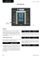
VSD DATA KEY (CON'T)
The next key press displays DC bus voltage for 2 and 3
compressor units.. On 4 compressor units, the 2nd mes-
sage will apply, since two DC bus voltages are present
(Systems 1/3 and 2/4).
VSD CURRENT LIMIT LOCAL = XXX %FLA
ISN = XXX
REMOTE = XXX %FLA
The next key press displays the Control Panel/VSD
Internal Ambient Temperature and VSD Cooling Pump/
Fan Status. YYY will indicate ON or OFF.
VSD DC BUS VOLTAGE = XXX VDC
The next key press displays the IGBT highest baseplate
temperature for 2 and 3 compressor units. 4 compres-
sor units display temperatures for Systems 1/3 (T1) and
Systems 2/4 (T2).
VSD DC BUS VOLTAGES BUS 1 = XXX VDC
BUS 2 = XXX VDC
VSD
COMP 3 MOTOR OVERLOAD = XXX AMPS
COMP 4 MOTOR OVERLOAD = XXX AMPS
VSD
COMP 1 MOTOR OVERLOAD = XXX AMPS
COMP 2 MOTOR OVERLOAD = XXX AMPS
VSD
INTERNAL AMBIENT TEMP = XXX.X °F
COOLING SYSTEM STATUS = YYY
VSD IGBT BASEPLATE TEMPS T1 = XXX °F
T2 = XXX °F
The next key press displays the state of the Precharge
signal, where XXX is either ON or OFF. The first dis
-
play is for 2 and 3 compressor units, the second display
shown is for 4 compressor units where Precharge 1 is
for compressors 1 and 3 DC Bus and Precharge 2 is for
compressors 2 and 4 DC Bus.
VSD
PRECHARGE SIGNAL = XXX
VSD
PRECHARGE 1 SIGNAL = XXX
VSD
PRECHARGE 2 SIGNAL = XXX
The next key press displays the setting of the VSD’s
105% FLA overload potentiometer for Compressor #1
and 2. The settings are determined by the adjustment of
the overload potentiometers on the VSD Logic Board.
These pots are factory set and should not require chang-
ing unless the circuit board is replaced. See TABLE 34
for factory settings.
The next key press displays the setting of the VSD’s
105% FLA potentiometer for Compressor #3 and #4 (3
and 4 compressor units only). The second line will be
blanked out on 3 compressor units.
8
Содержание YCAV0267E
Страница 61: ...61 JOHNSON CONTROLS FORM 201 21 NM3 616 This intentionally left blank 6 ...
Страница 63: ...63 JOHNSON CONTROLS FORM 201 21 NM3 616 ELEMENTARY CONTROL WIRING DIAGRAM 3 COMPRESSOR CON T LD12552 ...
Страница 67: ...67 JOHNSON CONTROLS FORM 201 21 NM3 616 LD12556 POWER ELEMENTARY DIAGRAM 3 COMPRESSOR YCAV CHILLER CON T 6 ...
Страница 72: ...72 JOHNSON CONTROLS FORM 201 21 NM3 616 035 20326 006 REV TECHNICAL DATA LD11125 LOCATION LABEL ...
Страница 73: ...73 JOHNSON CONTROLS FORM 201 21 NM3 616 This page intentionally left blank 6 ...
Страница 88: ...88 JOHNSON CONTROLS FORM 201 21 NM3 616 LOCATION LABEL TECHNICAL DATA 035 20890 008 REV LD11140 ...
Страница 89: ...89 JOHNSON CONTROLS FORM 201 21 NM3 616 6 035 20890 009 REV LOCATION LABEL CON T LD11141 ...
Страница 146: ...146 JOHNSON CONTROLS FORM 201 21 NM3 616 TECHNICAL DATA This page intentionally left blank ...
Страница 147: ...147 JOHNSON CONTROLS FORM 201 21 NM3 616 6 This page intentionally left blank ...
Страница 247: ...247 JOHNSON CONTROLS FORM 201 21 NM3 616 This page intentionally left blank ...
Страница 269: ...269 JOHNSON CONTROLS FORM 201 21 NM3 616 This page intentionally left blank 8 ...
Страница 289: ...289 JOHNSON CONTROLS FORM 201 21 NM3 616 8 This page intentionally left blank ...
Страница 317: ...317 JOHNSON CONTROLS FORM 201 21 NM3 616 8 This page intentionally left blank ...
Страница 348: ...348 JOHNSON CONTROLS FORM 201 21 NM3 616 MAINTENANCE NOTES ...
Страница 349: ...349 JOHNSON CONTROLS FORM 201 21 NM3 616 9 NOTES ...