


6.4 Fault Detection
YASKAWA ELECTRIC
SIEP C710616 30B YASKAWA AC Drive T1000A Technical Manual
287
Tr
ouble
s
ho
ot
in
g
6
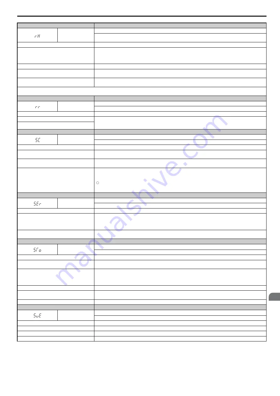
Digital Operator Display
Fault Name
rH
Braking Resistor Overheat
Braking resistor protection was triggered.
Fault detection is enabled when L8-01 = 1 (disabled as a default).
Cause
Possible Solution
Deceleration time is too short and excessive regenerative
energy is flowing back into the drive.
• Check the load, deceleration time, and speed.
• Reduce the load inertia.
• Increase the deceleration times (C1-02, C1-04, C1-06, C1-08, C1-09).
• Replace the braking option with a larger device that can handle the power that is discharged.
Excessive braking inertia.
Recalculate braking load and braking power. Reduce the braking load by adjusting braking resistor settings.
The braking operation duty cycle is too high.
Check the braking operation duty cycle. Braking resistor protection for ERF-type braking resistors (L8-01 = 1) allows a braking
duty cycle of maximum 3%.
The proper braking resistor has not been installed.
• Check the specifications and conditions for the braking resistor device.
• Select the optimal braking resistor.
Note:
The magnitude of the braking load trips the braking resistor overheat alarm, NOT the surface temperature. Using the braking resistor more frequently than it is rated for trips the alarm
even when the braking resistor surface is not very hot.
Digital Operator Display
Fault Name
rr
Dynamic Braking Transistor
The built-in dynamic braking transistor failed.
Cause
Possible Solution
The braking transistor is damaged.
• Cycle power to the drive and check if the fault reoccurs.
Refer to Diagnosing and Resetting Faults on page 303
• Replace either the control board or the entire drive. For instructions on replacing the control board, contact Yaskawa or your
nearest sales representative.
The control circuit is damaged.
Digital Operator Display
Fault Name
SC
Output Short-Circuit or IGBT Fault
The drive has detected an output short, a grounding fault, or an IGBT malfunction.
Cause
Possible Solution
Motor has been damaged from overheat or the motor
insulation has been weakened.
Check the motor insulation resistance and replace the motor if continuity is detected.
The cable is damaged and is coming into contact with
something causing a short-circuit.
Check the motor power cable and repair any short-circuits.
Hardware fault
A short-circuit or grounding fault on the drive output side has damaged the output transistors.
Make sure drive output is not shorted as follows:
B1
←→
U, V, W
←→
U, V, W
The above short-circuit will damage the output transistors.
Contact your Yaskawa representative or our sales offices for assistance.
Digital Operator Display
Fault Name
SEr
Too Many Speed Search Restarts
The number of Speed Search restarts exceeded the number set to b3-19.
Cause
Possible Solution
Speed Search parameters are set to the wrong values.
• Reduce the detection compensation gain during Speed Search (b3-10).
• Increase the current level when attempting Speed Search (b3-17).
• Increase the detection time during Speed Search (b3-18).
• Repeat Auto-Tuning.
The motor is coasting in the opposite direction of the
Run command.
Enable Bi-Directional Speed Search (b3-14 = 1).
Digital Operator Display
Fault Name
STo
Motor Pull Out or Step Out Detection
Motor pull out or step out has occurred. Motor has exceeded its pull-out torque.
Cause
Possible Solution
The wrong motor code is set (Yaskawa motors only).
• Enter the correct motor code for the PM being used into E5-01.
• For special-purpose motors, enter the correct data to all E5 parameters according to the test report provided for the motor.
Load is too heavy.
• Increase the load inertia for PM motor (n8-55).
• Increase the pull-in current during accel/decel (n8-51).
• Reduce the load.
• Increase the motor or drive capacity.
Load inertia is too heavy.
Increase the load inertia for PM motor (n8-55).
Acceleration and deceleration times are too short.
• Increase the acceleration and deceleration times (C1-01 through C1-08).
• Increase the S-curve acceleration and deceleration times (C2-01).
Speed response is too slow.
Increase the load inertia for PM motor (n8-55).
Digital Operator Display
Fault Name
SvE
Zero Servo Fault
Position deviation during zero servo.
Cause
Possible Solution
Torque limit is set too low.
Set the torque limit to an appropriate value using parameters L7-01 to L7-04.
Excessive load torque.
Reduce the amount of load torque.
Noise interference along PG encoder wiring.
Check the PG signal for noise interference.
–
Содержание T1000A
Страница 4: ...4 YASKAWA ELECTRIC SIEP C710616 30B YASKAWA AC Drive T1000A Technical Manual...
Страница 32: ...1 5 Component Names 32 YASKAWA ELECTRIC SIEP C710616 30B YASKAWA AC Drive T1000A Technical Manual...
Страница 104: ...4 10 Test Run Checklist 104 YASKAWA ELECTRIC SIEP C710616 30B YASKAWA AC Drive T1000A Technical Manual...
Страница 334: ...7 5 Drive Replacement 334 YASKAWA ELECTRIC SIEP C710616 30B YASKAWA AC Drive T1000A Technical Manual...
Страница 362: ...A 6 Drive Derating Data 362 YASKAWA ELECTRIC SIEP C710616 30B YASKAWA AC Drive T1000A Technical Manual...