


9.1 List of Parameters
9-31
9
Ap
pend
ix
Pn883
2
Communications Cycle Setting Monitor
[x transmission cycle]
(for maintenance, read only)
0 to 32
–
0
Immediately
Setup
–
Pn88A
2
MECHATROLINK Receive Error
Counter Monitor (for maintenance, read
only)
0 to 65535
–
0
Immediately
Setup
–
Pn890 to
Pn89E
4
Command Data Monitor at Alarm/Warn-
ing Occurs (for maintenance, read only)
0 to
FFFFFFFFH
–
0
Immediately
Setup
*1
Pn8A0 to
Pn8AE
4
Response Data Monitor at Alarm/Warn-
ing Occurs (for maintenance, read only)
0 to
FFFFFFFFH
–
0
Immediately
Setup
*1
Pn900
2
Parameter Bank Number
0 to 16
–
0
After restart
Setup
*1
Pn901
2
Parameter Bank Member Number
0 to 15
–
0
After restart
Setup
*1
Pn902 to
Pn910
2
Parameter Bank Member Definition
0000H to
08FFH
–
0
After restart
Setup
*1
Pn920 to
Pn95F
2
Parameter Bank Data (nonvolatile mem-
ory save disabled)
0000H to
FFFFH
–
0
Immediately
Setup
*1
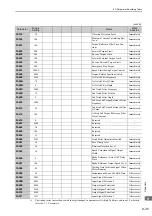
∗1.
For details, refer to the
Σ
-V Series/DC Power Input
Σ
-V Series/
Σ
-V Series for Large-Capacity Models User’s Man-
ual MECHATROLINK-II Commands
(Manual No.: SIEP S800000 54).
(cont’d)
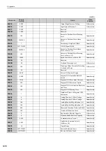
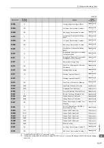
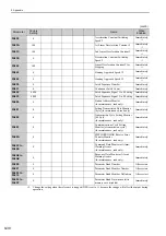
Parameter
No.
Size
Name
Setting
Range
Units
Factory
Setting
When
Enabled
Classi-
fication
Reference
Section
Содержание Sigma-V JUSP-MD D A Series
Страница 21: ...xxi Index Index 1 Revision History ...