


9.1 List of Parameters
9-25
9
Ap
pend
ix
Pn81E
2
Input Signal Monitor
Selection
–
–
0000
Immediately
Setup
*1
Pn81F
2
Command Data Allocation
–
–
0000
After restart
Setup
*1
Pn820
4
Forward Latching Allowable Area
-2147483648
to
2147483647
1
reference
unit
0
Immediately
Setup
*1
Pn822
4
Reverse Latching Allowable Area
-2147483648
to
2147483647
1
reference
unit
0
Immediately
Setup
*1
∗1.
For details, refer to the
Σ
-V Series/DC Power Input
Σ
-V Series/
Σ
-V Series for Large-Capacity Models User’s Man-
ual MECHATROLINK-II Commands
(Manual No.: SIEP S800000 54).
(cont’d)
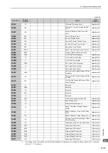
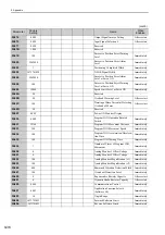
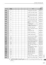
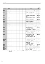
Parameter
No.
Size
Name
Setting
Range
Units
Factory
Setting
When
Enabled
Classi-
fication
Reference
Section
IO12 Signal Mapping
0
No mapping
1
Monitors CN1-40 input terminal.
2
Monitors CN1-41 input terminal.
3
Monitors CN1-42 input terminal.
4
Monitors CN1-43 input terminal.
5
Monitors CN1-44 input terminal.
6
Monitors CN1-45 input terminal.
7
Monitors CN1-46 input terminal.
IO13 Signal Mapping
0 to 7
Same as IO12 signal mapping.
IO14 Signal Mapping
0 to 7
Same as IO12 signal mapping.
IO15 Signal Mapping
0 to 7
Same as IO12 signal mapping.
4th 3rd 2nd 1st
digit digit digit digit
n.
4th
digit
3rd
digit
2nd
digit
1st
digit
n.
Option Field Allocation
0
1
Disables OPTION bit allocation.
Enables OPTION bit allocation.
Position Control Command TFF/TLIM Function Allocation
0
1
Disables allocation.
Enables allocation.
Reserved (Do not change.)
Reserved (Do not change.)
Содержание Sigma-V JUSP-MD D A Series
Страница 21: ...xxi Index Index 1 Revision History ...