


4 Operation
4.6.1 Connecting the Absolute Encoder
4-34
4.6.1
Connecting the Absolute Encoder
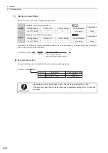
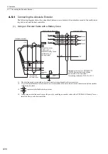
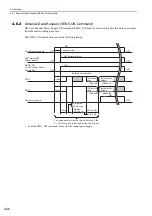
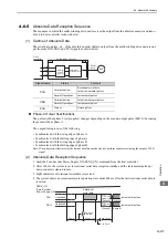
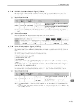
The following diagram shows the connection between a servomotor with an absolute encoder, the multi-wind-
ing drive unit, and the host controller.
(1) Using an Encoder Cable with a Battery Case
∗1.
The absolute encoder pin numbers for the connector wiring depend on the servomotors.
∗2.
To prevent the influence of external noise, we recommend you connect a ferrite core on the motor end of the encoder
cable using two turns.
∗3.
: represents shielded twisted-pair wires.
∗4.
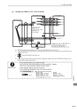
When using an absolute encoder, provide power by installing an encoder cable with a JUSP-BA01-E Battery Case or
install a battery on the host controller.
/PCO
33
34
35
36
19
20
CN1
SG
16
PAO
/PAO
PBO
/PBO
PCO
Battery
Multi-winding drive unit
Encoder cable
with battery case
Connector
shell
∗
3
0 V
Host controller
R
R
R
∗
4
ENC
3
4
CN21
Absolute encoder
Connector
shell
∗
3
∗
1
∗
2
5
6
1
2
PG5 V
PG0 V
PS
FG
/PS
BAT(+)
BAT(-)
Output line-driver
SN75ALS174
manufactured by Texas
Instruments or
the equivalent
Phase A
Phase B
Phase C
Phase A
Phase B
Phase C
Applicable line receiver: SN75ALS175
or MC3486 manufactured by Texas
Instruments or the equivalent
Terminating resistance R: 220 to 470
Ω
+ -
MECHA
Содержание Sigma-V JUSP-MD D A Series
Страница 21: ...xxi Index Index 1 Revision History ...