


4.10 Brake control
You can control a break via a digital input/output channel. For brake control you have the
following possibilities:
n
Braking via external brake
n
Quick stop via ramping
You have the possibility to control a brake via a digital input/output channel. By integration
into your user program, you can control it if necessary.
Quick stop is a ramp function, with which the connected motor can be decelerated and
brought to stop. During normal operation it is not necessary to activate this brake func-
tions manually, since normal braking operations are performed by the profile generator.
Quick stop is used when the operating conditions require a rapid stopping.
For quick stop there are the following possibilities:
n
Direct stop with short-circuit braking and subsequent state change to
‘Switch on
disabled’
.
n
Brake with quick stop deceleration and state change to
‘Switch on disabled’
.
Quick stop - objects
‘0x8100-01 - Control word’ on page 109
à
Quick stop configu-
ration
à
‘0x8100-02 - Status word’ on page 110
‘0x8200-01 - Configuration quick stop’
‘0x8580-03 - Deceleration quick stop
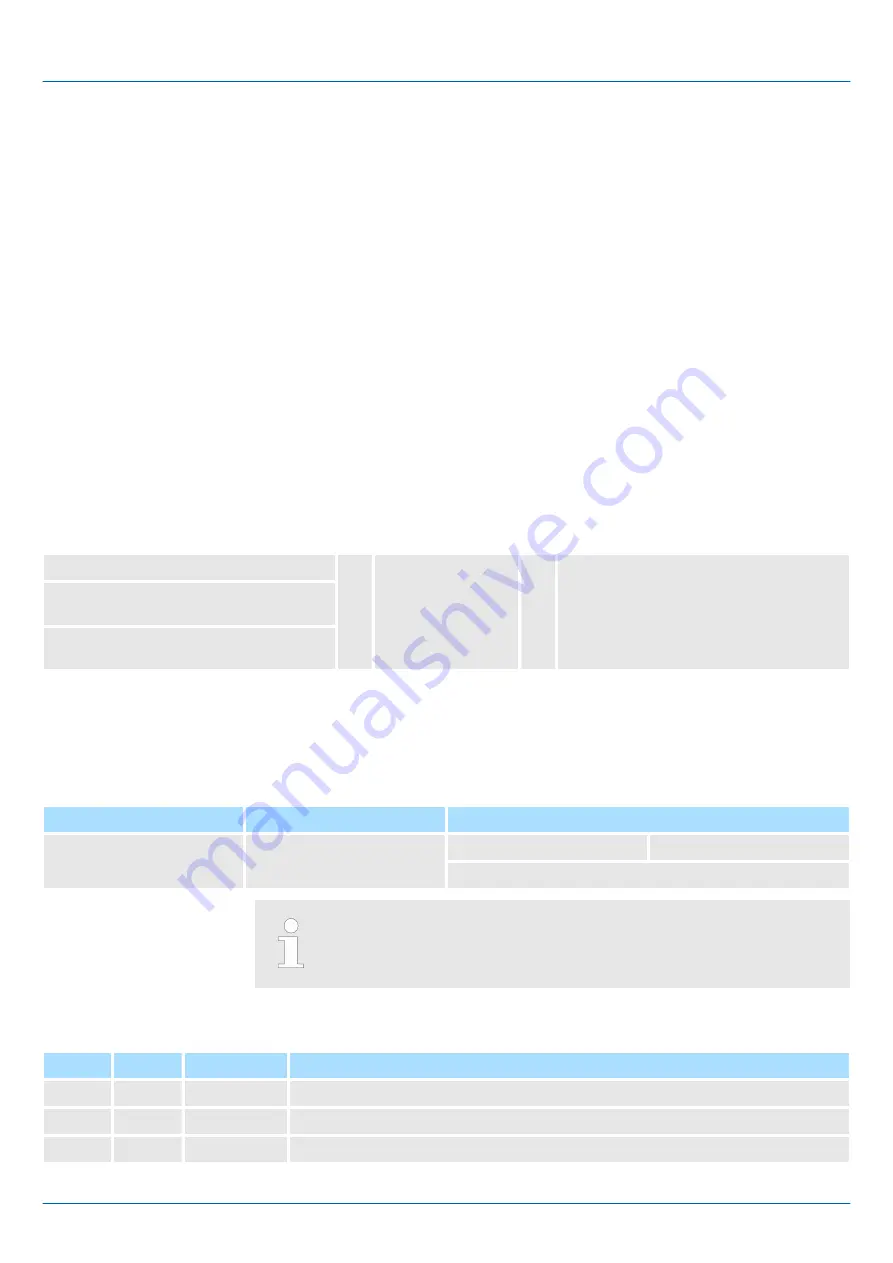
4.11 In-/Output area
The motion module uses 60byte input and 60byte output data.
Head module
Backplane bus
Motion module
CPU respectively bus cou-
pler
à
ß
Process data
Acyclic channel
60byte
The data exchange with the motion module must be consistent across
the 60 bytes! It is recommended to control it via the process image.
Input area
Offset
Size
Area
Description
0
2
Drive 1
‘0x8100-02 - Status word’ on page 110
2
2
Drive 1
‘0x8280-02 - Operating mode actual’ on page 119
4
4
Drive 1
‘0x8480-02 - Position actual value’ on page 124
Overview
Braking via external brake
Quick stop
Overview
VIPA System SLIO
Deployment
In-/Output area
HB300 | FM | 054-1CB00 | en | 18-06
83