Page 61
Component Removal
Integrated Modules
Integrated Modules
3-29
#826498 - Revision B - December, 2016
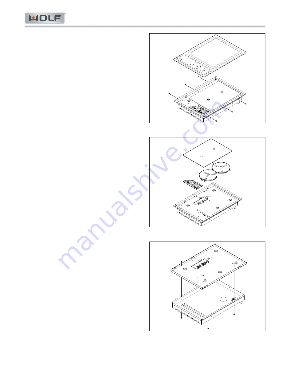
Induction Plate Assembly
To remove the induction plate assembly, first remove
the unit from the installation, then (See Figure 3-58):
1.
Use a T-20 Torx bit to extract the screws from the
side of the unit, directly below the induction plate.
2.
Remove the induction plate assembly from the unit.
Control Board
To remove the control board, first remove the induction
plate assembly, then (See Figure 3-59):
Remove the insulation from the unit.
1.
Disconnect the comm cable from the control board.
2.
2.
Depress the PCB standoff and lift the control
board off the PCB standoff. Repeat for the
remaining PCB standoffs.
3.
Remove the control board from the unit.
Induction Coil
To remove the induction coil, first remove the induction
plate assembly, then (See Figure 3-59):
Remove the insulation from the unit.
1.
Use a T-25 Torx bit to disconnect the induction coil
2.
wires from the generator.
2.
Disconnect the NTC connector from the generator.
3.
Use a T-25 Torx bit to extract the screw from the
ground plate.
4.
Remove the induction coil from the unit.
Generator Plate
To remove the generator plate, first remove the induc-
tion plate assembly, then (See Figure 3-60):
Remove the insulation from the unit.
1.
If the generator is being replaced, use a T-25 Torx
2.
bit to disconnect the induction coil wires from the
generator, and to extract the screw from the ground
plate.
3.
Remove the induction coils from the unit.
4.
Use a T-20 Torx bit to extract the screws that pass
up through the generator pan into the bottom of the
generator plate.
5.
Lift the generator plate, with the generator attached
from the generator pan.
6.
Disconnect the electrical wires from the terminal
block.
Figure 3-58. Induction Plate
Figure 3-59. Control Board and Coils
Figure 3-60. Generator Plate


