Page 48
Integrated Modules
Integrated Modules
Component Removal
3-16
#826498 - Revision B - December, 2016
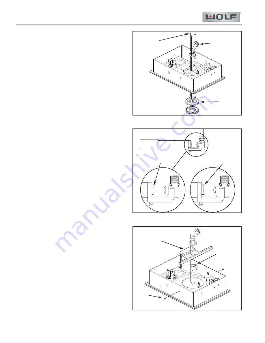
Burner Base and Venturi/Elbow Assembly
To remove the burner base and venturi/elbow assembly,
first remove the bottom base enclosure, then (See
Figure 3-28):
Use a 5/8” open end wrench to remove the gas line
1.
from the venturi/elbow assembly.
Support the burner base.
2.
Use a 5/16” nut driver to extract the three nuts hold-
3.
ing the venturi/elbow assembly to the bottom of the
pan.
The burner base will drop out.
4.
Remove the venturi/elbow assembly.
5.
NOTE:
The venturi/elbow assembly includes the spud
assembly (with jet), elbow assembly, and venturi, which
can be ordered separately.
Venturi Tube Setting
Figure 3-29 shows the position of the venturi tube for
LP and Natural gas. Verify the venturi tube setting
when converting the unit to a differnt gas, or reassem-
bling the venturi elbow assembly.
Side Bracket and Elbow Assembly Gasket
To remove the side bracket and access the elbow
assembly gasket, first remove the venturi/elbow assem-
bly, then (See Figure 3-30):
Using a Phillips screw driver extract the two Phillips
1.
screws from the side bracket.
Remove the side bracket.
2.
Elbow assembly gasket is located between the side
3.
bracket and the bottom of the unit pan.
Figure 3-28. Burner Base
Burner
Base
Figure 3-30. Side Bracket and Elbow Assy. Gasket
Phillips
Screws
Venturi
Elbow
Assembly
5/16”
Nuts
Side
Bracket
Elbow
Assembly
Gasket
Figure 3-29. Venturi Tube Setting
Natural
Setting
LP
Setting


