Page 47
Component Removal
Integrated Modules
Integrated Modules
3-15
#826498 - Revision B - December, 2016
Spark Module Removal
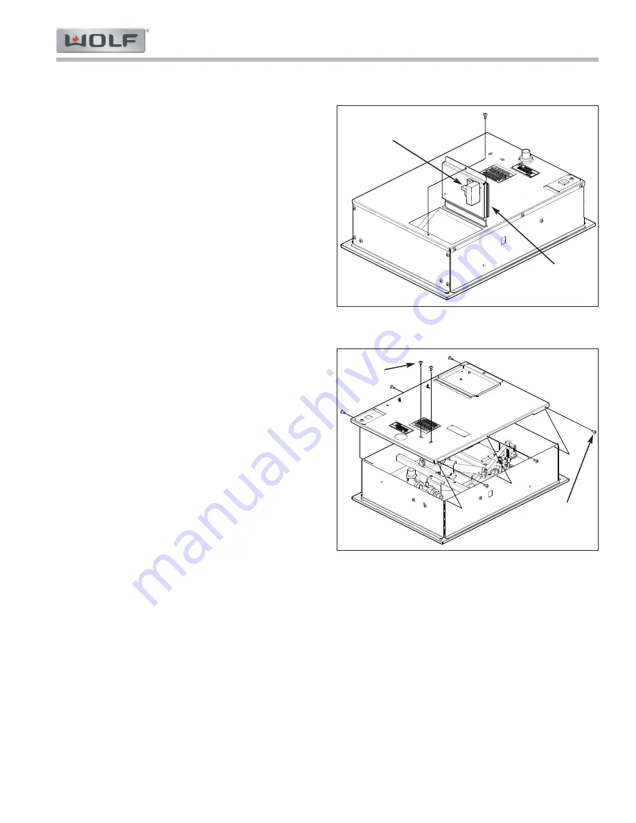
The spark module is accessible from the bottom of the
unit, without removing the unit from the installation.
Figure 3-26 shows the unit upside down, with the unit
bottom bracket opened to display the spark module. To
remove the spark module:
Use a Phillips screw driver to extract the screw
1.
holding the unit bottom bracket to the burner box.
Lower screw side of unit bottom bracket.
2.
Disconnect the electrode wire from the spark mod-
3.
ule.
Disconnect the connector from the spark module
4.
board.
Extract the two Phillips screws holding the spark
5.
module to the bottom module bracket.
NOTE:
Further access requires the removal of the unit
from the installation.
Bottom Base Enclosure
To access all other unit components except the spark
module, remove the unit from the installation. To
remove the bottom base enclosure, first remove the unit
from the installation, then (See Figure 3-27):
Use a Phillips screw driver to extract the six screws
1.
from the side of the bottom base enclosure.
Use a Phillips screw driver to extract the two
2.
screws holding the regulator bracket.
Disconnect the electrode wire from the spark mod-
3.
ule.
Disconnect the connector from the spark module
4.
board.
Use a 3/8” nut driver to remove the ground wire nut
5.
and remove the wires.
Disconnect the power supply harness.
6.
Remove the wire harness from the wire manage-
7.
ment clips.
Figure 3-26. Unit Bottom Bracket
Component Removal - MM15TF/S
Figure 3-27. Bottom Base Enclosure
Spark
Module
Unit
Bottom
Bracket
Spark
Module
Screws
Bottom
Base
Screws


