


Logical Command and Speed Reference
CFW500 | 7-11
7
and
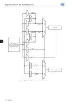
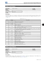
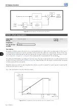
show the operation of the Multispeed, considering digital
inputs programmed for NPN in P0271. Although the most relevant digital input can be programmed in DI1, DI2,
DI5 or DI6, only one of those options is allowed; otherwise, the config status (CONF), according to
SITUATIONS FOR CONFIG STATUS on page 5-6
, is activated to indicate parameterization incompatibility.
Acceleration
ramp
Time
Active
Active
Inactive
Inactive
DI3 or DI7
DI4 or DI8
DI5 or DI6
DI1 or DI2
P0124
P0126
P0127
P0128
P0129
P0130
P0131
Inactive
Active
Output
frequency
P0125
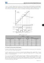
Figure 7.4:
Operating graph of the Multispeed function
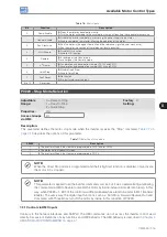
Table 7.3:
Multispeed speeds
8 Speeds
4 Speeds
2 Speeds
DI1 or DI2 or DI5 or DI6
DI3 or DI7
DI4 or DI8
Speed Reference
Open
Open
Open
P0124
Open
Open
0 V
P0125
Open
0 V
Open
P0126
Open
0 V
0 V
P0127
0 V
Open
Open
P0128
0 V
Open
0 V
P0129
0 V
0 V
Open
P0130
0 V
0 V
0 V
P0131
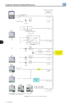
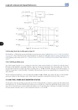
7.2.4 Reference via Electronic Potentiometer
The Electronic Potentiometer function (E.P.) allows the speed reference to be set by means of two digital inputs
(one to increment it and another to decrement it).
In order to enable this function, you must first configure the speed reference via E.P., making P0221 = 7 and/or
P0222 = 7. After enabling this function, just program two digital inputs (P0263 to P0270) in 11 or 33 (Accelerate
E.P.) and 12 or 34 (Decelerate E.P.).
show the operation of the E.P. function using DI3 as Accelerate E.P. (P0265 = 11), DI4
as Decelerate E.P. (P0266 = 12) and DI1 as Run/Stop (P0263 = 1). In this example, the reference reset is done
with the inverter disabled and activating both Accelerate and Decelerate E.P. inputs. Besides, you can monitor
the action of the inputs individually, as well as the action of the reference backup (P0120 = 1) when the Run/Stop
command is opened and closed again.
Содержание CFW500 V1.8X
Страница 2: ......
Страница 4: ......
Страница 8: ...Contents...
Страница 34: ...General Information 2 4 CFW500...
Страница 38: ...About the CFW500 3 4 CFW500 3...
Страница 42: ...HMI and Basic Programming 4 4 CFW500 4...
Страница 52: ...Programming Basic Instructions 5 10 CFW500 5...
Страница 56: ...Identification of the Inverter Model and Accessories 6 4 CFW500 6...
Страница 76: ...Available Motor Control Types 8 4 CFW500 8...
Страница 84: ...V f Scalar Control 9 8 CFW500 9...
Страница 170: ...Communication 17 8 CFW500 17...