


Fault and Alarms
15-4 | CFW500
15
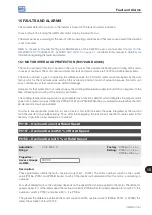
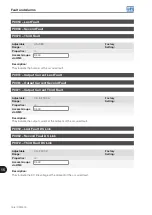
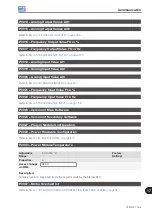
P0343 – Mask for Faults and Alarms
Adjustable
Range:
Bit 0 = F0074
Bit 1 = F0048
Bit 2 = F0078
Bit 3 = F0079
Bit 4 = F0076
Bit 5 = F0179
Bit 6 to 15 = Reserved
Factory
Setting:
0007h
Properties:
cfg
Access Groups
via HMI:
Description:
Parameter P0343 allows deactivating some faults and alarms specific of the inverter. By means of a bit mask, a
binary number is formed, where the “Bit” equivalent to “0” disables the respective fault or alarm. Note that the
numeric representation of P0343 is hexadecimal.
ATTENTION!
Disable the ground fault or overload protections may damage the inverter. Only do that under WEG
technical directions.
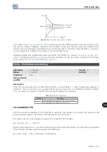
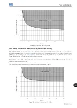
15.3 MOTOR OVERTEMPERATURE PROTECTION (F0078)
This function protects the motor against overtemperature through indication of fault F0078.
The motor needs a temperature sensor of the triple PTC type. The reading of the sensor can be done in two
different ways: through the analog input or through the digital input.
For the reading of the PTC via analog input, it is necessary to configure it for current input and select option
“4 = PTC” in P0231, P0236 or P0241. Connect the PTC between 10 Vdc and the analog input, as well
as close the AIx configuration DIP-Switch in "mA".
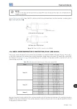
The analog input reads the PTC resistance and compares it to the limits values for the fault. When those values
are exceeded, fault F0078 is indicated, as shown in
ATTENTION!
The PTC must have reinforced electrical insulation up to 1000 V.
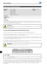
Table 15.1:
Actuation level of fault F0078 PTC via analog input
PTC Resistance
AIx
Overtemperature
R
PTC
< 50 Ω
V
IN
> 9.1 V
F0078
50 Ω < R
PTC
< 3.9 kΩ
9.1 V > V
IN
> 1.3 V
Standard
R
PTC
> 3.9 kΩ
V
IN
< 1.3 V
F0078
NOTE!
For this function to work properly, it is important to keep the gain(s) and offset(s) of the analog inputs
at the standard values.
For the PTC via digital input it is necessary to set the option 29 (PTC) in the DIx programming in P0263 to P0270,
and connect the PTC to the referred digital input and to the GND. The resistance levels of the triple PTC are the
same as those of the analog input in
, but the short-circuit of PTC (R
PTC
< 50 Ω) cannot
be detected, and thus it is seen as normal operation. Only the case R
PTC
> 3.9 kΩ activates fault F0078.
Содержание CFW500 V1.8X
Страница 2: ......
Страница 4: ......
Страница 8: ...Contents...
Страница 34: ...General Information 2 4 CFW500...
Страница 38: ...About the CFW500 3 4 CFW500 3...
Страница 42: ...HMI and Basic Programming 4 4 CFW500 4...
Страница 52: ...Programming Basic Instructions 5 10 CFW500 5...
Страница 56: ...Identification of the Inverter Model and Accessories 6 4 CFW500 6...
Страница 76: ...Available Motor Control Types 8 4 CFW500 8...
Страница 84: ...V f Scalar Control 9 8 CFW500 9...
Страница 170: ...Communication 17 8 CFW500 17...