


HMI and Basic Programming
CFW500 | 4-3
4
Level 2
allows browsing the parameters of the group selected by
level 1
.
Level 3
, in turn, allows the modification of the parameter selected in
level 2
. At the end of this level, the modified
value is saved or not if the key ENTER or ESC is pressed, respectively.
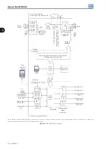
The
illustrates the basic browsing of the operating modes of the HMI.
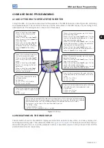
Monitoring Mode
It is the initial status of the HMI after the powering up and of the initialization
screen, with factory default values.
The field menu is not active in this mode.
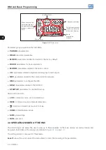
The fields main display, secondary display of the HMI and monitoring
bar indicate the values of three parameters predefined by P0205, P0206
and P0207.
From the monitoring mode, when you press the
ENTER/MENU
key, you
commute to the setting mode.
Monitoring
Parameterization
Level 1
Parameterization
Level 2
Parameterization
Level 3
BACK
ESC
BACK
ESC
BACK
ESC
ENTER
MENU
ENTER
MENU
ENTER
MENU
Setting Mode
Level 1:
This is the first level of the setting mode. It is possible to choose the
parameter group using the keys
and
.
The fields: main display, secondary display, bar graph for monitoring of
variable and measurement units are not shown in this level.
Press the
ENTER/MENU
key to go to level 2 of the setting mode –
parameter selection.
Press the
BACK/ESC
key to return to the monitoring mode.
Level 2:
The number of the parameter is shown on the main display and its content
on the secondary display.
Use the
and
keys to find the desired parameter.
Press the
ENTER/MENU
key to go to level 3 of the setting mode –
modification of the parameter content.
Press the
BACK/ESC
key to return to level 1 of the setting mode.
Level 3:
The content of the parameter is shown on the main display and the number
of the parameter is shown on the secondary display.
Use the
and
keys to configure the new value for the selected
parameter.
Press the
ENTER/MENU
key to confirm the modification (save the new
value) or
BACK/ESC
to cancel the modification (not save the new value).
In both cases, the HMI returns to level 2 of the setting mode.
Figure 4.3:
HMI operating modes
NOTE!
When the inverter is in the Fault state, the main display indicates the number of the fault in the format
Fxxxx
. The browsing is allowed after pressing the ESC key, and the indication
Fxxxx
goes to the
secondary display until the fault is reset.
NOTE!
When the inverter is in the Alarm state, the main display indicates the number of the alarm in the
format
Axxxx
. The browsing is allowed after pressing any key, and the indication
Axxxx
goes to
the secondary display until the situation causing the alarm is solved.
Содержание CFW500 V1.8X
Страница 2: ......
Страница 4: ......
Страница 8: ...Contents...
Страница 34: ...General Information 2 4 CFW500...
Страница 38: ...About the CFW500 3 4 CFW500 3...
Страница 42: ...HMI and Basic Programming 4 4 CFW500 4...
Страница 52: ...Programming Basic Instructions 5 10 CFW500 5...
Страница 56: ...Identification of the Inverter Model and Accessories 6 4 CFW500 6...
Страница 76: ...Available Motor Control Types 8 4 CFW500 8...
Страница 84: ...V f Scalar Control 9 8 CFW500 9...
Страница 170: ...Communication 17 8 CFW500 17...