


Rheostatic Braking
CFW500 | 14-1
14
14 RHEOSTATIC BRAKING
The braking torque that may be obtained by the application of frequency inverters, without rheostatic braking
resistors, varies from 10 % to 35 % of the motor rated torque.
In order to obtain higher braking torques, resistors for rheostatic braking are used. In this case, the regenerated
energy is dissipated in the resistor mounted outside the inverter.
This kind of braking is used in cases where short deceleration times are desired or when high-inertia loads are
driven.
The Rheostatic Braking function can only be used if a braking resistor is connected to the inverter, and if the
parameters related to it are properly set.
P0153 – Rheostatic Braking Level
Adjustable
Range:
339 to 1200 V
Factory
Setting:
375 V (P0296 = 0)
750 V (P0296 = 1)
950 V (P0296 = 2)
Properties:
Access Groups
via HMI:
MOTOR
Description:
Parameter P0153 defines the voltage level to activate the braking IGBT, and it must be compatible with the
power supply.
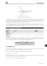
If P0153 is set at a level too close to the overvoltage actuation level (F0022), it may occur before the braking
resistor can dissipate the motor regenerated energy. On the other hand, if the level is too lower than the
overvoltage, the function limits the actuation at a maximum of 15 % of the overvoltage level.
Thus, it is ensured that the braking resistor will not actuate in the DC link rated operating region; refer to
. Therefore, although P0153 has a wide setting band (339 to 1200 V), only the values defined
by the actuation band in
are effective, that is, values below the actuation band are
internally limited in the execution of the function and values above naturally deactivate the function.
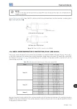
Table 14.1:
Rheostatic Braking actuation value
Input Voltage
Rated DC Link
P0153 Actuation
Band
P0153 Factory
Default
200 to 240 Vac
339 Vdc
349 to 410 Vdc
375 Vdc
380 to 480 Vac
678 Vdc
688 to 810 Vdc
750 Vdc
500 to 600 Vac
846 Vdc
850 to 1000 Vdc
950 Vdc
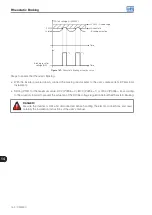
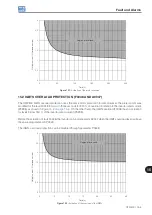
shows an example of typical Rheostatic Braking actuation, where it can be observed
the hypothetical wave shapes of the voltage on the braking resistor and the voltage on the DC link. Thus, when
the braking IGBT connects the link to the external resistor, the DC link voltage drops below the value set by
P0153, keeping the level below fault F0022.
Содержание CFW500 V1.8X
Страница 2: ......
Страница 4: ......
Страница 8: ...Contents...
Страница 34: ...General Information 2 4 CFW500...
Страница 38: ...About the CFW500 3 4 CFW500 3...
Страница 42: ...HMI and Basic Programming 4 4 CFW500 4...
Страница 52: ...Programming Basic Instructions 5 10 CFW500 5...
Страница 56: ...Identification of the Inverter Model and Accessories 6 4 CFW500 6...
Страница 76: ...Available Motor Control Types 8 4 CFW500 8...
Страница 84: ...V f Scalar Control 9 8 CFW500 9...
Страница 170: ...Communication 17 8 CFW500 17...