


Fault and Alarms
CFW500 | 15-5
15
NOTE!
The DI2 is the only one that cannot be used as PTC input, because it has input circuit dedicated to
frequency input (FI).
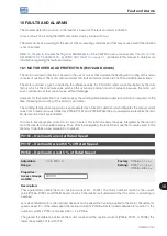
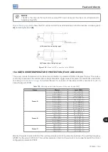
shows the PTC connection to the inverter terminals for both situations: via analog input
(a)
and via digital input
(b)
.
+10 V
AIx
(DIP SWITCH = mA)
DIx
PTC
PTC
(a) Connection via analog input
(b) Connection via digital input
GND
Figure 15.3:
(a) and (b) PTC connection to the CFW500
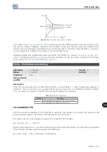
15.4 IGBTS OVERTEMPERATURE PROTECTION (F0051 AND A0050)
The power module temperature is monitored and indicated in parameter P0030 in degrees Celsius. This value is
constantly compared to the overtemperature fault and alarm trigger value of the power module F0051 and A0050,
according to
where the level for actuation of the alarm A0050 is fixed at 5 ºC (41 °F)
below the level of F0051.
Table 15.2:
Overtemperature actuation levels of the power module F0051
Frame
Model
Level F0051
Frame A
1.6 A / 200 V
80 °C (176 °F)
2.6 A / 200 V
80 °C (176 °F)
4.3 A / 200 V
80 °C (176 °F)
7.0 A / 200 V
93 °C (199.4 °F)
9.6 A / 200 V
100 °C (212 °F)
1.0 A / 400 V
97 °C (206.6 °F)
1.6 A / 400 V
97 °C (206.6 °F)
2.6 A / 400 V
97 °C (206.6 °F)
4.3 A / 400 V
97 °C (206.6 °F)
6.1 A / 400 V
123 °C (253.4 °F)
Frame B
7.3 A / 200 V
85 °C (185 °F)
10 A / 200 V
95 °C (203 °F)
16 A / 200 V
110 °C (230 °F)
2.7 A / 400 V
105 °C (221 °F)
4.3 A / 400 V
105 °C (221 °F)
6.5 A / 400 V
105 °C (221 °F)
10 A / 400 V
110 °C (230 °F)
Frame C
24 A / 200 V
120 °C (248 °F)
14 A / 400 V
110 °C (230 °F)
16 A / 400 V
110 °C (230 °F)
Besides the alarm indication A0050, the overtemperature protection automatically reduces the switching frequency
(P0297) for the value of 2500 Hz. This overtemperature protection characteristic can be deactivated in the control
configuration parameter P0397.
Содержание CFW500 V1.8X
Страница 2: ......
Страница 4: ......
Страница 8: ...Contents...
Страница 34: ...General Information 2 4 CFW500...
Страница 38: ...About the CFW500 3 4 CFW500 3...
Страница 42: ...HMI and Basic Programming 4 4 CFW500 4...
Страница 52: ...Programming Basic Instructions 5 10 CFW500 5...
Страница 56: ...Identification of the Inverter Model and Accessories 6 4 CFW500 6...
Страница 76: ...Available Motor Control Types 8 4 CFW500 8...
Страница 84: ...V f Scalar Control 9 8 CFW500 9...
Страница 170: ...Communication 17 8 CFW500 17...