


About the CFW500
3-2 | CFW500
3
= Human-machine interface
Analog input
(AI1)
(*)
Digital inputs
(DI1 to DI4)
(*)
Power supplies for electronics and interfaces
between power and control
RS-485
PC
POWER
Single-phase /
three-phase
rectifier
Internal
RFI filter
(available
in the
inverters
CFW500...
C...)
Motor
U/T1
V/T2
W/T3
DC+
DC-
BR
Inverter with
IGBT transistors
and current
feedback
Power
supply
R/L1/L
S/L2/N
T/L3
= DC link connection
= braking resistor connection
Pre-
charge
Software WLP
SUPERDRIVE
(*)
MODBUS
D
C l
in
k c
ap
ac
ito
r b
an
k
B
ra
ki
ng I
G
B
T (
av
ai
la
bl
e i
n
in
ve
rt
er
s C
FW
50
0.
..D
B
...
)
CPU
32 bits
"RISC"
EEPROM
(memory)
User’s
plug-in
card
Interfaces
(RS-232,
RS-485
or USB)
Analog output
(AO1)
(*)
Supply 24 V
Supply 10 V
Digital output
DO1 (RL1)
Digital output
DO2 (TR)
(*)
HMI
(remote)
Voltage
feedback
PE
PE
Memory card
(MMF)
Accessory
CONTROL
CONTROL
STANDARD PLUG-IN
HMI
(*)
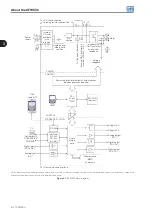
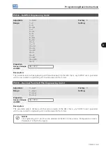
The number of analog and digital inputs and outputs, may vary according to the plug-in used. For further information, refer to the installation, configuration
and operation guide of the accessory with plug-in module used.
Figure 3.1:
CFW500 block diagram
Содержание CFW500 V1.8X
Страница 2: ......
Страница 4: ......
Страница 8: ...Contents...
Страница 34: ...General Information 2 4 CFW500...
Страница 38: ...About the CFW500 3 4 CFW500 3...
Страница 42: ...HMI and Basic Programming 4 4 CFW500 4...
Страница 52: ...Programming Basic Instructions 5 10 CFW500 5...
Страница 56: ...Identification of the Inverter Model and Accessories 6 4 CFW500 6...
Страница 76: ...Available Motor Control Types 8 4 CFW500 8...
Страница 84: ...V f Scalar Control 9 8 CFW500 9...
Страница 170: ...Communication 17 8 CFW500 17...