


Rheostatic Braking
14-2 | CFW500
14
U
d
rated
DC link voltage (U
d
)(P0004)
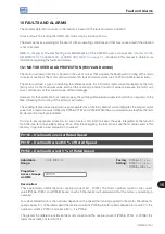
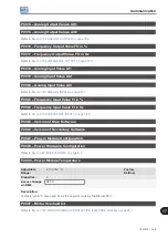
F0022 - Overvoltage
Rheostatic
Braking actuation
Time
Time
U
d
U
d
P0153
Braking resistor
voltage (BR)
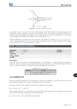
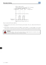
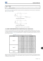
Figure 14.1:
Rheostatic Braking actuation curve
Steps to enable the Rheostatic Braking:
With the inverter powered down, connect the braking resistor (refer to the user’s manual, item 3.2 Electrical
Installation).
Setting P0151 for the maximum value: 410 V (P0296 = 0), 810 V (P0296 = 1) or 1200 V (P0296 = 3), according
to the situation, in order to prevent the actuation of the DC link voltage regulation before the Rheostatic Braking.
DANGER!
Be sure the inverter is OFF and disconnected before handling the electric connections and read
carefully the installation instructions of the user's manual.
Содержание CFW500 V1.8X
Страница 2: ......
Страница 4: ......
Страница 8: ...Contents...
Страница 34: ...General Information 2 4 CFW500...
Страница 38: ...About the CFW500 3 4 CFW500 3...
Страница 42: ...HMI and Basic Programming 4 4 CFW500 4...
Страница 52: ...Programming Basic Instructions 5 10 CFW500 5...
Страница 56: ...Identification of the Inverter Model and Accessories 6 4 CFW500 6...
Страница 76: ...Available Motor Control Types 8 4 CFW500 8...
Страница 84: ...V f Scalar Control 9 8 CFW500 9...
Страница 170: ...Communication 17 8 CFW500 17...