


PID Controller
13-10 | CFW500
13
Description:
It defines how the PID feedback or process variable will be presented in P0040, as well as the PID Setpoint in
P0041. Therefore, the PID feedback or process variable full scale which corresponds to 100.0 % in P0525, in
the analog input (AI1 or AI3) or in the frequency input (FI) used as feedback of the PID controller is indicated in
P0040 and P0041 in the scale defined by P0528 and P0529.
Example: the pressure transducer operates at 4-20 mA for a band of 0 to 25 bars; setting of parameter P0528
at 250 and P0529 at 1.
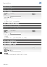
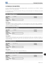
P0529 – Process Variable Indication Form
Adjustable
Range:
0 = wxyz
1 = wxy.z
2 = wx.yz
3 = w.xyz
Factory
Setting:
1
Properties:
Access Groups
via HMI:
HMI
Description:
This parameter allows setting the form of indication of the PID process variable (P0040) and PID setpoint
(P0041).
P0533 – X Process Variable Value
Adjustable
Range:
0.0 to 100.0 %
Factory
Setting:
90.0 %
Properties:
Access Groups
via HMI:
I/O
Description:
These parameters are used in the digital output functions (refer to
Section 12.6 DIGITAL OUTPUTS on page
) with the purpose of signaling/alarm. In order to do so, you must program the Digital Output function
(P0275...P0279) at 22 = Process Variable > VPx, or at 23 = Process Variable < VPx.
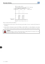
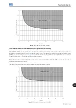
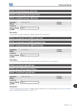
P0535 – Wake Up Band
Adjustable
Range:
0.0 to 100.0 %
Factory
Setting:
0.0 %
Properties:
Access Groups
via HMI:
I/O
Description:
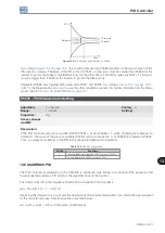
It is the process variable error in relation to the PID setpoint to enter and exit the Sleep mode. The value of
P0535 is expressed in % of the full scale (P0528) like the scale of P0525, that is:
Error =
· 100 %
P0041 - P0040
P0528
The parameter P0535 ensures that, besides the conditions defined by P0217 and P0218, the PID controller
error is in an acceptable range around the Setpoint so as to allow the inverter to go into the Sleep mode
(disabling the motor), as shown by
.
Содержание CFW500 V1.8X
Страница 2: ......
Страница 4: ......
Страница 8: ...Contents...
Страница 34: ...General Information 2 4 CFW500...
Страница 38: ...About the CFW500 3 4 CFW500 3...
Страница 42: ...HMI and Basic Programming 4 4 CFW500 4...
Страница 52: ...Programming Basic Instructions 5 10 CFW500 5...
Страница 56: ...Identification of the Inverter Model and Accessories 6 4 CFW500 6...
Страница 76: ...Available Motor Control Types 8 4 CFW500 8...
Страница 84: ...V f Scalar Control 9 8 CFW500 9...
Страница 170: ...Communication 17 8 CFW500 17...