


Digital and Analog Inputs and Outputs
12-4 | CFW500
12
P0232 – AI1 Input Gain
P0237 – AI2 Input Gain
P0242 – AI3 Input Gain
Adjustable
Range:
0.000 to 9.999
Factory
Setting:
1.000
P0234 – AI1 Input Offset
P0239 – AI2 Input Offset
P0244 – AI3 Input Offset
Adjustable
Range:
-100.0 to 100.0 %
Factory
Setting:
0.0 %
P0235 – AI1 Input Filter
P0240 – AI2 Input Filter
P0245 – AI3 Input Filter
Adjustable
Range:
0.00 to 16.00 s
Factory
Setting:
0.00 s
Properties:
Access Groups
via HMI:
I/O
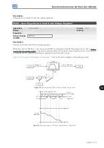
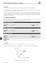
Description:
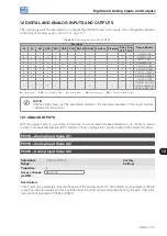
Each analog input of the inverter is defined by the steps of calculation of signal, OFFSET, gain, filter, function
and value AIx, as shown in
:
Input
AI1
(*)
AI2
(*)
AI3
(*)
Gain
AI1 – P0232
AI2 – P0237
AI3 – P0242
OFFSET
AI1 – P0234
AI2 – P0239
AI3 – P0244
AI1 – P0235
AI2 – P0240
AI3 – P0245
AI1 – P0018
AI2 – P0019
AI3 – P0020
Function
AI1 – P0231
AI2 – P0236
AI3 – P0241
Filter
Value AIx
(internal)
Signal
AI1 – P0233
AI2 – P0238
AI3 – P0243
(*)
Control terminals available in the plug-in module.
Figure 12.2:
Block diagram of the analog inputs - AIx
Содержание CFW500 V1.8X
Страница 2: ......
Страница 4: ......
Страница 8: ...Contents...
Страница 34: ...General Information 2 4 CFW500...
Страница 38: ...About the CFW500 3 4 CFW500 3...
Страница 42: ...HMI and Basic Programming 4 4 CFW500 4...
Страница 52: ...Programming Basic Instructions 5 10 CFW500 5...
Страница 56: ...Identification of the Inverter Model and Accessories 6 4 CFW500 6...
Страница 76: ...Available Motor Control Types 8 4 CFW500 8...
Страница 84: ...V f Scalar Control 9 8 CFW500 9...
Страница 170: ...Communication 17 8 CFW500 17...