


Logical Command and Speed Reference
7-10 | CFW500
7
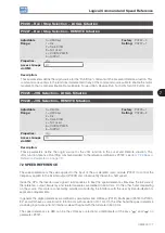
P0124 – Multispeed Reference 1
Adjustable
Range:
-500.0 to 500.0 Hz
Factory
Setting:
3.0 Hz
P0125 – Multispeed Reference 2
Adjustable
Range:
-500.0 to 500.0 Hz
Factory
Setting:
10.0 (5.0) Hz
P0126 – Multispeed Reference 3
Adjustable
Range:
-500.0 to 500.0 Hz
Factory
Setting:
20.0 (10.0) Hz
P0127 – Multispeed Reference 4
Adjustable
Range:
-500.0 to 500.0 Hz
Factory
Setting:
30.0 (20.0) Hz
P0128 – Multispeed Reference 5
Adjustable
Range:
-500.0 to 500.0 Hz
Factory
Setting:
40.0 (30.0) Hz
P0129 – Multispeed Reference 6
Adjustable
Range:
-500.0 to 500.0 Hz
Factory
Setting:
50.0 (40.0) Hz
P0130 – Multispeed Reference 7
Adjustable
Range:
-500.0 to 500.0 Hz
Factory
Setting:
60.0 (50.0) Hz
P0131 – Multispeed Reference 8
Adjustable
Range:
-500.0 to 500.0 Hz
Factory
Setting:
66.0 (55.0) Hz
Properties:
Access Groups
via HMI:
Descriptions:
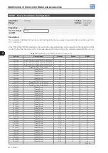
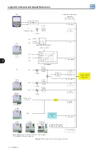
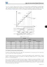
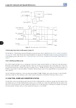
By the combination of up to three digital inputs, one from eight levels that form the Multispeed reference is
selected. Read the description of the digital input in
Section 12.5 DIGITAL INPUTS on page 12-14
, as well as the
reference selection in
Section 7.1 SELECTION FOR LOGICAL COMMAND AND SPEED REFERENCE on page
. The negative values determine a direction of rotation opposite to that defined by the inverter command
word (Bit 2 of P0682 and P0684).
Содержание CFW500 V1.8X
Страница 2: ......
Страница 4: ......
Страница 8: ...Contents...
Страница 34: ...General Information 2 4 CFW500...
Страница 38: ...About the CFW500 3 4 CFW500 3...
Страница 42: ...HMI and Basic Programming 4 4 CFW500 4...
Страница 52: ...Programming Basic Instructions 5 10 CFW500 5...
Страница 56: ...Identification of the Inverter Model and Accessories 6 4 CFW500 6...
Страница 76: ...Available Motor Control Types 8 4 CFW500 8...
Страница 84: ...V f Scalar Control 9 8 CFW500 9...
Страница 170: ...Communication 17 8 CFW500 17...