


0
Quick Reference of Parameters, Alarms and Faults
0-18 | CFW500
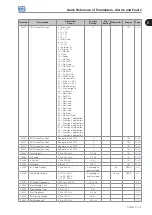
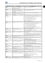
Fault / Alarm
Description
Possible Causes
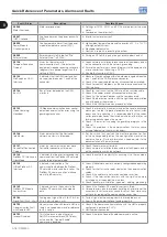
A0046
Motor Overload
Motor overload alarm.
Settings of P0156, P0157, and P0158 are too low for the used
motor.
Overload on the motor shaft.
A0047
IGBT Overload
Overload alarm on the power pack with
IGBTs.
Inverter output overcurrent.
A0050
Power Module
Overtemperature
Overtemperature alarm from the power
module temperature sensor (NTC).
High ambient temperature around the inverter (>50 °C (> 122 °F))
and high output current.
Blocked or defective fan.
Heatsink is too dirty, preventing the air flow.
A0090
External Alarm
External alarm via DIx (option "No
External Alarm" in P026x).
Wiring on DI1 to DI8 inputs are open or have poor contact.
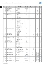
A0128
Telegram Reception
Timeout
Alarm that indicates serial
communication fault. It indicates the
equipment stopped receiving valid serial
telegrams for a period longer than the
setting in P0314.
Check network installation, broken cable or fault/poor contact
on the connections with the network, grounding.
Ensure the master always sends telegrams to the equipment in
a time shorter than the setting in P0314.
Disable this function in P0314.
A0133
No Supply on CAN
Interface
It indicates that the CAN interface has
no supply between pins 1 and 5 of the
connector.
Measure if there is voltage within the allowed range between the
pins 1 and 5 of the CAN interface connector.
Check if the supply cables are not misconnected or inverted.
Check for contact problems on the cable or connector of the
CAN interface.
A0134
Bus Off
Bus off error detected on the CAN
interface.
Check for short-circuit on the CAN circuit transmission cable.
Check if the cables are not misconnected or inverted.
Check if all the network devices use the same baud rate.
Check if the termination resistors with the right value were installed
only at the end of the main bus.
Check if the CAN network was properly installed.
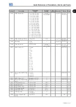
A0135
Node Guarding/
Heartbeat
CANopen communication error control
detected communication error using the
guarding mechanism.
Check the times set on the master and on the slave to exchange
messages. In order to prevent problems due to transmission
delays and time counting, it is recommended that the values
set for error detection by the slave be multiples of the times set
for message exchange on the master.
Check if the master is sending the guarding telegrams in the
time set.
Check the problems in the communications that may cause
missing telegrams or transmission delays.
A0136
Idle Master
Alarm indicates that the DeviceNet
network master is in Idle mode.
Set the switch that controls the master operation for Run
or the corresponding bit on the configuration word of the
master software. If further information is needed, refer to the
documentation of the master used.
A0137
DeviceNet Connection
Timeout
Alarm that indicates that one or more
DeviceNet connections timed out.
Check the network master status.
Check network installation, broken cable or fault/poor contact
on the connections with the network.
A0138
Profibus DP Interface in
Clear Mode
It indicates that the inverter received the
command from the Profibus DP network
master to go into clear mode.
Check the network master status, ensuring it is in the run mode.
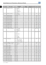
A0139
Offline Profibus DP
Interface
It indicates interruption in the
communication between the Profibus
DP network master and the inverter. The
Profibus DP communication interface
went into offline status.
Check if the network master is correctly configured and operating
properly.
Check for short-circuit or poor contact on the communication
cables.
Check if the cables are not misconnected or inverted.
Check if the termination resistors with the right value were
installed only at the end of the main bus.
Check the network installation in general – cabling, grounding.
A0140
Profibus DP Module
Access Error
It indicates error in the access to the
Profibus DP communication module
data.
Check if the Profibus DP module is correctly fitted.
Hardware errors due to improper handling or installation of the
accessory, for instance, may cause this error. If possible, carry
out tests by replacing the communication accessory.
A0163
Signal Fault AIx 4..20 mA
Analog input signal AIx at 4 to 20 mA or
20 to 4 mA is below 2 mA.
Current signal on the analog input AIx interrupted or null.
Error in the parameterization of analog input AIx.
A0700
Communication Fault
with Remote HMI
No communication with remote HMI, but
there is no speed command or reference
for this source.
Check if the communication interface with the HMI is properly
configured in parameter P0312.
HMI cable disconnected.
A0702
Inverter Disabled
This failure occurs when there is a
SoftPLC movement block (REF block)
active and the “General Enable”
command is disabled.
Check if the drive General Enable command is active.
Содержание CFW500 V1.8X
Страница 2: ......
Страница 4: ......
Страница 8: ...Contents...
Страница 34: ...General Information 2 4 CFW500...
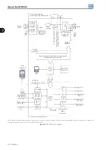
Страница 38: ...About the CFW500 3 4 CFW500 3...
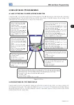
Страница 42: ...HMI and Basic Programming 4 4 CFW500 4...
Страница 52: ...Programming Basic Instructions 5 10 CFW500 5...
Страница 56: ...Identification of the Inverter Model and Accessories 6 4 CFW500 6...
Страница 76: ...Available Motor Control Types 8 4 CFW500 8...
Страница 84: ...V f Scalar Control 9 8 CFW500 9...
Страница 170: ...Communication 17 8 CFW500 17...