F
−
1031, Section 4321
Page 46 of 57
Install Discharge Manifold
(Either Rotation)
1. Install the two (2) O-rings in the volute body bores.
2. Install the single O-ring in the groove on the manifold pilot diameter.
3. Install the discharge manifold on the pump body aligning the manifolds with the volute body bores.
4. Install the four (4) hex head screws and lockwashers. Torque to 25 lb-ft (34 N•m).
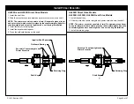
Volute Body
O-ring,
3-5/8 x 3-7/8 in.
(2) O-rings,
1-3/4 x 2 in
.
(4) M12-1.75 x 120 mm
Hex Head Screws and
Lockwashers
Interstage / Discharge
Manifold Assembly
Interstage / Discharge
Manifold Assembly
Volute Body
(4) M12-1.75 x 120 mm
Hex Head Screws and Lock
washers
O-ring,
3-5/8 x 3-7/8 in.
(2) O-rings,
1-3/4 x 2 in.
CW Impeller Rotation
(Reference Page 43)
CCW Impeller Rotation
(Reference Page 43)
Содержание HL Series
Страница 52: ...F 1031 Section 4321 Page 52 of 57 Reassembly Cross Section Views HL200D and HL300D Direct Drive Models...
Страница 53: ...F 1031 Section 4321 Page 53 of 57 HL200K and HL300K Gear Drive Models...
Страница 54: ...F 1031 Section 4321 Page 54 of 57 HL400D Direct Drive Model...
Страница 55: ...F 1031 Section 4321 Page 55 of 57 HL400K Gear Drive Model...

