F
−
1031, Section 4321
Page 41 of 57
Reassembly
Install Separator Plate
NOTE: Long M12 bolts may be installed in the two (2) M12-1.75 tapped
holes and used as handles to guide the separator plate into the pump.
1. Locate the marking indicating the up position of the separator plate.
2. Install separator plate over the impeller shaft and hub of the high pres
sure impeller. The up marking must be facing out and point in the direc
tion of the pump discharge.
3. Install the twelve (12) socket head screws and washers using Blue Loc
tite. Torque to 40-45 lb-ft (54-61 N•m).
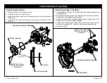
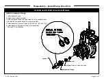
1. Install the small O-ring on the impeller shaft and the larger O-ring in the
back side of the impeller.
2. Install the impeller on the shaft, engaging the key.
3. Install the impeller washer. The washer faces must be orientated so the
cam faces engage. See Washer Detail.
4. Install the impeller locknut.
5. Restrain the companion flange on the drive end of the pump from moving
and torque locknut to 140-150 lb-ft 9190-203 N•m).
Install Main Stage Impeller
Separator Plate
Temporary Guide Screw
(12) M12-1.75 x 55 mm Socket
Head Screws and Washers
Temporary
Guide
Screw
Shaft O-ring,
13/16 x 15/16 in.
Impeller O-ring,
2 x 2-3/16 in.
Impeller
Locknut
Impeller
Impeller
Washer
Impeller O-ring
Shaft
O-ring
Содержание HL Series
Страница 52: ...F 1031 Section 4321 Page 52 of 57 Reassembly Cross Section Views HL200D and HL300D Direct Drive Models...
Страница 53: ...F 1031 Section 4321 Page 53 of 57 HL200K and HL300K Gear Drive Models...
Страница 54: ...F 1031 Section 4321 Page 54 of 57 HL400D Direct Drive Model...
Страница 55: ...F 1031 Section 4321 Page 55 of 57 HL400K Gear Drive Model...


