F
−
1031, Section 4321
Page 42 of 57
Reassembly
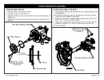
Install Intake Fitting
1. Install the O-ring in the groove on the intake fitting.
2. Carefully install the intake adapter over the impeller shaft. The end of the
impeller shaft must nest into the internal bearing in the intake adapter.
3. Temporarily install two (2) hex head screws without washers on opposite
side of the intake fitting.
4. Tighten the two (2) screws to bring the intake flange in contact with the
volute body flange.
5. Rotate the impeller shaft. There should be no contact between the im
peller and wear ring in the intake adapter.
a.
If there is no contact, install the twelve (12) screws and lockwashers
and tighten evenly from side to side. Torque to 67 lb-ft (91 N•m).
b.
If there is contact, correct before proceeding. Check the following
causes of the contact:
1.
Raised burr or nick on either the impeller hub or wear ring.
2.
Wear ring was cocked when installed in intake adapter and is
deformed sufficiently to contact the impeller.
c.
Once the contact issue is resolved, install the twelve (12) screws
and lockwashers an tighten evenly from side to side. Torque to 67
lb-ft (91 N•m).
6. HL400 Series Models Only: If the outer fitting was removed, install the
fitting with the O-ring. Torque the four (4) screws to 67 lb-ft (91 N•m).
O-ring,
11 x 11-3/8 in.
(12) M12-1.75 x 30 mm
Hex Head Screws and Lockwashers
Intake Fitting
O-ring,
5-1/2 x 5-3/4 in.
(4) M12-1.75 x 30 mm
Hex Head Screws and Lockwashers
Outer Fitting
HL400 Series Models Only
Содержание HL Series
Страница 52: ...F 1031 Section 4321 Page 52 of 57 Reassembly Cross Section Views HL200D and HL300D Direct Drive Models...
Страница 53: ...F 1031 Section 4321 Page 53 of 57 HL200K and HL300K Gear Drive Models...
Страница 54: ...F 1031 Section 4321 Page 54 of 57 HL400D Direct Drive Model...
Страница 55: ...F 1031 Section 4321 Page 55 of 57 HL400K Gear Drive Model...


