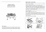
FP3005
pilot with sparker
Sensor
Sparker
FP3005
IPI Pilot
FP1943
pilot flame
Thermopile
Thermocouple
FP1943
Millivolt Control Pilot
Figure 80 –
Burner Flame Appearance
LG1182
36CFDV log flames
LG1182
CFDV Series Gas Fireplace
48
20306739
FINAL INSTALLATION
PILOT FLAME
The flames from the pilot should be visually checked as
soon as the heater is installed and periodically during
normal operation.
Figure 79.
The pilot flame must always
be present when the fireplace is in operation.
The pilot
flame has three distinct flames, one engulfing the thermo
-
pile, one engulfing the thermocouple or sensor, and the
other reaching to the main burner.
Figure 79 –
Pilot Flame
BURNER FLAME
The flames from the burner should be visually checked
as soon as the heater is installed and periodically during
normal operation. In normal operation, at full rate, and after
operating for about 15 to 30 minutes, the flame should be
yellow.
Figure 80
If the flame is blue and only in the center, turn off unit and
let cool. After unit is cool, remove logs and check to make
sure rock wool is placed correctly. Replace logs.
NOTE:
The type of installation, vent system configuration,
and wind effects may cause the flame patterns to vary.
INSTALLING PORCELAIN LINER KIT
Kit contents:
• One (1) Right panel
• One (1) Left panel
• One (1) Rear panel
• Four (4) Self-drilling #8 screws
NOTE:
If logs are being used, porcelain panels must be
installed first.
1. Remove safety barrier, glass frame, and stones, fire
-
glass or logs (if applicable).
2. Remove top heat shield.
3. Place rear panel against the center of the rear wall of
the firebox.
4. Place left and right panels against firebox sides and at
-
tach top flanges of the panels using self-drilling screws
provided.
5. Replace stones, fireglass and/or logs as applicable
and re-install glass frame and safety barrier.
Read these instructions carefully before be
-
ginning to install the panels. Please check
your fireplace size and model number to verify
the correct kit part number.
IMPORT
ANT
NOTE
Some fireplace systems may require removal of
a screen panel, glass front, log assembly or en
-
gine assembly before you can install the pan
-
els. Please refer to the homeowner's manual for
further instruction.
Turn off, unplug, and allow the fireplace to cool be
-
fore installing the panels. Only a qualified service
person should service and repair the fireplace. A
qualified service person must connect and dis
-
connect the fireplace to the gas supply. Follow all
local codes.
Always handle the panels with two hands. Do not
force the panels into place. Excessive force will
break the panels. Always wash hands after han
-
dling the panels.
WARNING
PILOT FLAME
Firebrick and porcelain liner kits are approved to be used
with with your fireplace. Before you begin installation, en
-
sure that you have the correct size liner kit for your fire
-
place.
Содержание 33CFDVNI
Страница 66: ...CFDV Series Gas Fireplace 66 20306739...
Страница 67: ...CFDV Series Gas Fireplace 20306739 67...


