14
SAFETY SWITCH SYSTEM TEST
WARNING:
A qualified trained
person must check the safety switch
system for proper function before oper-
ating the machine. There is a problem
in the safety switch circuit if the LEDs
are not lit as indicated or, if having
opened or removed a cover or guard
equipped with a switch, the machine
can be started. DO NOT operate the
machine in this condition! Operating
the machine in this condition could
result in serious injury such as amputa-
tion! Call a qualified electrician to
locate and repair the fault. See “Electri-
cal Assembly”, page 46.
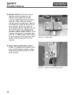
1.
With all covers and guards in place,
turn the power disconnect/lockout
switch to “
I
” (ON) and press the top
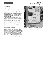
reset button. Only the green “relay con-
dition” LEDs on the amplifier should be
lit (Figure 11, page 15). Push the
“IMPELLER START” button. Machine
should start. (See “Troubleshooting”,
page 50 if machine does not start.)
Push the “IMPELLER STOP” button
and turn power disconnect/lockout
switch to “
O
” (OFF). Visually verify
machine has come to a complete stop.
WARNING:
Be careful to avoid
contact with cutting parts and sharp
edges exposed during the safety switch
system test. Contact with cutting parts
and sharp edges could result in serious
injury such as amputation.
2.
Remove the cutting enclosure.
Turn
power disconnect/lockout switch to “
I
”
(ON) and press the top reset button.
Only the red “relay condition” LEDs and
the red “switch output” LEDs corre-
sponding to the switch on the removed
or opened cover or guard should be lit
on the amplifier. If LEDs are lit cor-
rectly, push the “IMPELLER START”
button. The safety switch circuit has
been interrupted and machine should
NOT start. If the machine does start,
that safety circuit has failed. Push the
“IMPELLER STOP” button, then
dis-
connect and lock out power source.
Call a qualified electrician to locate and
repair the fault immediately.
3.
Turn the power disconnect/lockout
switch to “O” (OFF)
and replace or
close the cover or guard.
4.
Remove the feed adapter
and repeat
steps 2 and 3. Make sure all covers
and guards are securely in place and
closed after safety switch system has
been tested.
SAFETY
Safety Switch System
Содержание COMITROL 2100
Страница 2: ......
Страница 28: ...Addendum A 26 This page intentionally left blank...
Страница 84: ...6 This page intentionally left blank...
Страница 94: ...16 This page intentionally left blank...
Страница 95: ...17 GENERAL INFORMATION...
Страница 101: ...23 INSTALLATION...
Страница 104: ...26 This page intentionally left blank...
Страница 110: ...32 This page intentionally left blank...
Страница 131: ...53 PARTS...
Страница 132: ...54 This page intentionally left blank...
Страница 134: ...56 PARTS Tools See the Addendum for updated information...
Страница 138: ...60 PARTS Agitator Feed Screw See the Addendum for updated information...
Страница 140: ...62 PARTS Cutting Assembly 8 3 4 5 2 5 1 6 7 9 12 11 10 14 16 26 25 24 23 22 21 17 18 19 20 13 15...
Страница 146: ...PARTS Motor and Drive Parts 68 See the Addendum for updated information...
Страница 148: ...PARTS Electrical Assembly NEMA 70 See the Addendum for updated information...
Страница 150: ...PARTS Electrical Assembly NEMA 72 59 58 57 17 16 15 1 14 See the Addendum for updated information...
Страница 152: ...PARTS Electrical Assembly CE compliant 74 See the Addendum for updated information...
Страница 156: ...78 PARTS Electrical Assembly Switches See the Addendum for updated information...
Страница 165: ......

