37
3.
Stop the machine. Turn power dis-
connect/lockout switch to “O” (OFF)
and lock out.
After machine has come
to a complete stop, press the “I”
(IMPELLER START) button to verify
machine will not start before opening or
removing any cover or guard.
4.
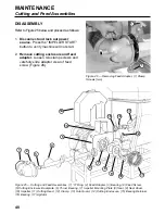
Remove the cutting enclosure and
feed adapter
(see “Disassembly”,
page 40). Thoroughly wash all sheet
metal covers (see “Opening or Remov-
ing”, page 34.)
5.
Remove and disassemble the
cutting parts.
See pages 40 and 41.
Thoroughly wash all cutting parts with
water or appropriate cleaning solution.
If cleaning solutions are used, rinse
thoroughly.
6.
Clean remaining portion of machine.
A forceful stream of water will remove
most of the product. Use cleaning solu-
tions when necessary and rinse thor-
oughly.
SAFETY SIGNS
WARNING:
Safety signs are placed
on machines to help users avoid per-
sonal injury. If the machine does not
have these signs or if they are no
longer legible do not use the machine.
Install or replace the signs immediately.
INSPECTION
Safety signs:
Inspect all safety signs
on machine for damage. Damaged, loose,
illegible or missing signs must be replaced.
See “Safety Signs and Machine Labels”,
pages 84 & 85 for sign placement and part
number information.
INSTALLATION
1.
Clean mounting surfaces.
Remove all
traces of old sign material and adhe-
sives, oils, cleaning material and water.
Remove any nicks or burrs. For
machines in cold room temperature,
warm the mounting surface so that the
label will adhere properly.
2.
Wipe mounting surface of machine
with isopropyl alcohol. (Consult manu-
facturer’s Material Safety Data Sheet
for proper handling of isopropyl
alcohol.) Remove sign backing and
apply label to dry, lint free mounting
surface, starting at one end of label
and rolling to other end to help avoid
air bubbles. For maximum bond
strength, rub mounted label with a
clean dry cloth and apply moderate
heat (100–130°F, 38–54°C).
MAINTENANCE
Cleaning and Safety Signs
Содержание COMITROL 2100
Страница 2: ......
Страница 28: ...Addendum A 26 This page intentionally left blank...
Страница 84: ...6 This page intentionally left blank...
Страница 94: ...16 This page intentionally left blank...
Страница 95: ...17 GENERAL INFORMATION...
Страница 101: ...23 INSTALLATION...
Страница 104: ...26 This page intentionally left blank...
Страница 110: ...32 This page intentionally left blank...
Страница 131: ...53 PARTS...
Страница 132: ...54 This page intentionally left blank...
Страница 134: ...56 PARTS Tools See the Addendum for updated information...
Страница 138: ...60 PARTS Agitator Feed Screw See the Addendum for updated information...
Страница 140: ...62 PARTS Cutting Assembly 8 3 4 5 2 5 1 6 7 9 12 11 10 14 16 26 25 24 23 22 21 17 18 19 20 13 15...
Страница 146: ...PARTS Motor and Drive Parts 68 See the Addendum for updated information...
Страница 148: ...PARTS Electrical Assembly NEMA 70 See the Addendum for updated information...
Страница 150: ...PARTS Electrical Assembly NEMA 72 59 58 57 17 16 15 1 14 See the Addendum for updated information...
Страница 152: ...PARTS Electrical Assembly CE compliant 74 See the Addendum for updated information...
Страница 156: ...78 PARTS Electrical Assembly Switches See the Addendum for updated information...
Страница 165: ......


