A.15
Addendum
Manual Page Number
Revision
Maintenance, Electrical Assembly
(continued)
: Add the following.
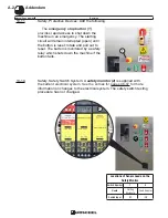
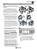
Current Transformer and Motor Load
Indicator
The
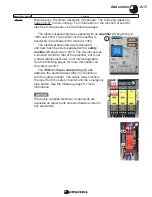
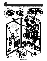
current transformer (1)
measures
the current being drawn by the motor. The
transformer is connected to the
motor load
indicator (2)
and must be properly configured
for the electrical specifications of your machine.
Replacing the Current Transformer
1.
Disconnect the
primary wire (3)
from the
circuit breaker. Note the number of times
the wire is wound through the transformer.
The top illustration shows examples of
primary windings with values of 1 and 2.
2.
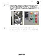
Disconnect the
secondary wires (4)
from the transformer terminals. Note the
number of times the wire is wound through
the transformer and to which terminals the
wires are connected (one secondary wire is
shown in color in the illustration for clarity;
both wires are black).
3.
Install the replacement transformer
with
the
XI and HI marks (5)
face up.
4.
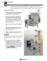
Wind the primary wire through the
transformer.
Refer to your notes from
Step 1 or see the Current Transformer
Windings Chart included in this addendum.
A small section of the
chart (6)
is shown
at the right; see the columns indicated by
the arrows. See the motor name plate to
determine the full load amps or check the
amperage rating of the circuit breaker as
described on the previous page.
5.
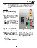
Wind the secondary wire through the
transformer.
The wire wound through
the transformer connects to the
positive
terminal (7)
on the motor load indicator.
Refer to your notes from Step 2 or see the
Current Transformer Windings Chart in this
addendum for the number of windings. See
the column in the chart titled “CT WIND”.
If the value from the chart is negative,
connect the wire to the
XI terminal (8)
on the current transformer. If the value is
positive, connect the wire to the
HI terminal
(9)
. Connect the remaining wire to the other
terminal.
(–)
(+)
1
5
5
3
7
9
2
4
8
6
Full Load
Amps
MCCB1
Size
MCCB1
Part Number
Im
Setting
CT WIND
PRI
SEC
46
125 A
21932
5
2
-2
47
2
-2
48
2
-1
49
2
-1
50
2
0
(See page A.39: Current Transformer Windings
Chart for the complete chart.)
Содержание COMITROL 2100
Страница 2: ......
Страница 28: ...Addendum A 26 This page intentionally left blank...
Страница 84: ...6 This page intentionally left blank...
Страница 94: ...16 This page intentionally left blank...
Страница 95: ...17 GENERAL INFORMATION...
Страница 101: ...23 INSTALLATION...
Страница 104: ...26 This page intentionally left blank...
Страница 110: ...32 This page intentionally left blank...
Страница 131: ...53 PARTS...
Страница 132: ...54 This page intentionally left blank...
Страница 134: ...56 PARTS Tools See the Addendum for updated information...
Страница 138: ...60 PARTS Agitator Feed Screw See the Addendum for updated information...
Страница 140: ...62 PARTS Cutting Assembly 8 3 4 5 2 5 1 6 7 9 12 11 10 14 16 26 25 24 23 22 21 17 18 19 20 13 15...
Страница 146: ...PARTS Motor and Drive Parts 68 See the Addendum for updated information...
Страница 148: ...PARTS Electrical Assembly NEMA 70 See the Addendum for updated information...
Страница 150: ...PARTS Electrical Assembly NEMA 72 59 58 57 17 16 15 1 14 See the Addendum for updated information...
Страница 152: ...PARTS Electrical Assembly CE compliant 74 See the Addendum for updated information...
Страница 156: ...78 PARTS Electrical Assembly Switches See the Addendum for updated information...
Страница 165: ......


