


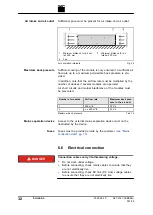


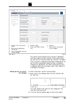


Connection diagram
1
Mains
2
Mains and system protection
3
Fuses / power circuit breakers
4
Contactor supply
5
Mains contactor
6
AC-DC module
7
DC link
8
24 VDC supply voltage
9
Circuit breaker for mains volt-
age measurement
10 Mains voltage measurement
11 Contact for contactor release
12 Potential equalization
Electrical connection
Fig. 26
The following components are not part of the AC-DC module,
but must rather be provided by the customer:
■
Mains and system protection (2)
(If residual current circuit breakers are used: use type B.)
■
Fuses / power circuit breakers (3)
(see "Mains connection data", pg. 15)
■
Mains contactor (5)
−
Dielectric strength corresponding to mains voltage: 400 /
480 V ±10%
−
Current-carrying capacity: 64 A
−
Operation mode: AC-3
■
24 VDC supply voltage (8)
36
Installation
2020-06-10
A67-0141-00.BKEN-
001-05
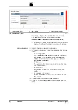
Customer area
Содержание TruConvert AC 3025
Страница 1: ...Operator s manual TruConvert AC 3025 TruConvert System Control...
Страница 2: ......
Страница 6: ...II Good to know 2020 06 10 A67 0141 00 BKEN 001 05...


