background image

Protective measures taken by the 
manufacturer

The AC-DC module is installed in an enclosed metal casing.

1.8

What you must know as an operator

1. The AC-DC module must not be opened. 

There are no parts within the device that can be serviced by 
the user.

2. Only operate the AC-DC module within the conditions descri-

bed in chapter "Technical specifications".

3. Only operating personnel 

without

 pacemaker or implants 

may work in the operational site.

4. For the electrical connection, use only cables that are in per-

fect condition and have the correct dimensions.

5. Periodically retest acc. to DGUV regulation 3 (DGUV = Deut-

sche Gesetzliche Unfallversicherung – German Statutory 
Accident Insurance Association).

8

Safety

2020-06-10

A67-0141-00.BKEN-

001-05

Содержание TruConvert AC 3025

Страница 1: ...Operator s manual TruConvert AC 3025 TruConvert System Control...

Страница 2: ......

Страница 3: ...Operator s manual TruConvert AC 3025 TruConvert System Control Original operator s manual Edition 2020 06 10...

Страница 4: ...Address for orders TRUMPF H ttinger GmbH Co KG Technische Redaktion B tzinger Stra e 80 D 79111 Freiburg Fon 49 761 8971 0 Fax 49 761 8971 1150 Internet http www trumpf huettinger com E Mail info ele...

Страница 5: ...vice depart ment The serial number can be found on the name plate of the device How to reach our Service department 49 761 8971 2170 49 761 8971 1178 Service Elektronik de trumpf com A67 0141 00 BKEN...

Страница 6: ...II Good to know 2020 06 10 A67 0141 00 BKEN 001 05...

Страница 7: ...ation 9 2 2 Function description 9 2 3 Configurations 9 2 4 Construction 12 Overview 13 Rear side 13 Display elements 14 3 Technical specifications 15 3 1 Data TruConvert AC 3025 15 3 2 TruConvert Sys...

Страница 8: ...tion 41 7 1 Commissioning 41 Performing initial commissioning 41 7 2 Operation via web based user interface 45 Calling up the web based user interface 45 Menu structure 47 7 3 Operation via Modbus 47...

Страница 9: ...work settings 65 7 12 Software update 66 Perform software update 66 7 13 Device information 67 Displaying device information 67 7 14 State diagram 68 8 Maintenance 69 8 1 Periodic check of the environ...

Страница 10: ...cription DANGER Indicates a major danger If it is not avoided serious injuries or death will result WARNING Indicates a dangerous situation If it is not avoided it may lead to serious injuries CAUTION...

Страница 11: ...ithstand voltage Operation at more than 2000 m above sea level Outdoors Failure to observe pollution degree 2 environmental con dition In an explosive environment 1 4 Authorized personnel Installation...

Страница 12: ...ng signs on the AC DC module Fig 1 1 6 What you must know as an operator Note All warning signs must be present and legible If one or more of these warning signs is missing or not legible contact TRUM...

Страница 13: ...These voltages occur both in the AC DC module as well as at the outputs of the AC DC module The AC DC module s connection cables carry voltages that are life threatening A person who comes into contac...

Страница 14: ...AC DC module within the conditions descri bed in chapter Technical specifications 3 Only operating personnel without pacemaker or implants may work in the operational site 4 For the electrical connec...

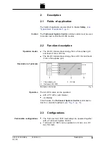
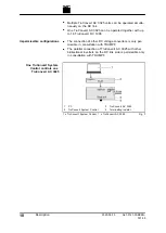
Страница 15: ...ds it into a three phase grid 1 Three phase grid 2 TruConvert AC 3025 3 DC link Description of principle Fig 2 The AC DC module can be operated with a PC with a web browser via Modbus In both cases th...

Страница 16: ...ion with TRUMPF The parallel connection of TruConvert AC 3025 with other bidirectional inverters on the DC link side is permissible only in consultation with TRUMPF 1 PC 2 TruConvert System Control 3...

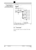
Страница 17: ...r 2 TruConvert System Control 3 DC link 4 Terminating resistor 1 x TruConvert System Control n x TruConvert AC 3025 Fig 4 A67 0141 00 BKEN 001 05 2020 06 10 Description 11 One TruConvert System Contro...

Страница 18: ...Control controls one TruCon vert AC 3025 and m x TruConvert DC 1008 Fig 5 2 4 Construction The AC DC module is housed in an enclosed 19 inch metal housing 12 Description 2020 06 10 A67 0141 00 BKEN 00...

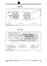
Страница 19: ...ntactor release contact and mains voltage measurement Contactor Mains Measure ment 3 24 V supply voltage 4 DC link voltage DC Link 5 LED status display 6 Data cable MASTER OUT 7 Threaded bolts for pot...

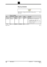
Страница 20: ...ing Operation 1 green on Flashing off Flashing Flashing 2 yellow Flashing Flashing off off LED indicates the energy direction Illuminates if the energy flows from mains to the DC link Flashes if the e...

Страница 21: ...ging discharging nominal appa rent power 25 kVA Asymmetrical load Up to 8 3 kVA phase Charging discharging power factor cos 1 to 1 Inductive and capacitive phase shift Nominal current for listed volta...

Страница 22: ...e N N conductor and PE conductor are not connected in the TruCon vert AC 3025 N conductor and PE conductor must be connected outside of the TruConvert AC 3025 Ground leakage current 3 mA If residual c...

Страница 23: ...ameters form the basis for dimensioning Internal resistances of the sour ces present in the DC link Capacitances present in the DC link Inductivities present in the DC link Taking into account aging a...

Страница 24: ...actor release Contactor Mains Measurement PCB plug connector 10 pin Recommended external fuses Circuit breaker 4 pin Current I 1 A For region EN IEC Voltage V 400 V Rated switching capacity acc to IEC...

Страница 25: ...x 129 mm x 500 mm Dimensions of front panel W x H 482 mm x 132 mm Weight 27 kg Housing material Galvanized sheet steel Protection class IP 20 Housing Tab 8 Dimensional drawing Fig 10 A67 0141 00 BKEN...

Страница 26: ...V supply voltage DC 24 V DC 10 250 mA PCB plug connector 2 pin Ethernet interface 1 Connection for web based user interface or Modbus TCP UDP RJ 45 RS 485 interface Connection for TruCon vert AC 3025...

Страница 27: ...n 5 C to 65 C 23 F to 149 C 5 90 Up to approx 78 kPa 2000 m high above sea level Pollution degree 2 Storage 20 C to 80 C 4 F to 176 F 5 90 Trans port 20 C to 80 C 4 F to 176 F 90 Environmental conditi...

Страница 28: ...use 5 x 10 mm2 5 x AWG 8 With 40 A external fuse 5 x 6 mm2 5 x AWG 10 Cable requirement for mains connection Tab 13 The information applies to Ambient temperature 30 C 86 F Cable operating temperature...

Страница 29: ...ation Fig 13 M6 threaded bolt torque 5 Nm 1 x 4 mm2 1 x AWG 10 4 3 DC link Fig 14 At the AC DC module Phoenix PCB plug connector Required counterpart connector 3pin 76 A IPC 16 3 STF 10 16 A67 0141 00...

Страница 30: ...contact TRUMPF Service Note To keep inductivity at a minimum cables should be twisted 4 4 Contactor release contact and mains voltage measurement Contactor release contact and mains voltage measureme...

Страница 31: ...art 2 pin connector 16A GMSTB 2 5 HCV 2 ST 7 62 LR 2 x 1 5 mm2 2 x AWG 16 The 24V supply voltage is necessary for supplying the following components of the AC DC module Control Fan Driver of power sta...

Страница 32: ...DC DC module Notes The total length of the data cable from the system control to the last DC DC module via the AC DC module must not exceed 30 m If no further DC DC module is connected to the DC DC m...

Страница 33: ...net Ethernet data connection Fig 21 RJ 45 male connector Twisted pair patch cable in accordance with standard TIA EIA 568A B CAT 5 or higher Max length 100 m Note The total length of the data cable mu...

Страница 34: ...RJ 45 male connector Twisted pair patch cable in accordance with standard TIA EIA 568A B CAT 5 or higher Max length 30 m 28 Interfaces 2020 06 10 A67 0141 00 BKEN 001 05 Connection Cable requirement...

Страница 35: ...on EU directives Low voltage directive 2014 35 EU Electromagnetic compatibility directive 2014 30 EU Standards taken into account EN 62040 2 2006 AC class C2 EN 62109 1 2010 UL 1741 A67 0141 00 BKEN 0...

Страница 36: ...5 2 EU declaration of conformity TruConvert AC 3025 EU declaration of conformity TruConvert AC 3025 Fig 23 30 Standards and directives 2020 06 10 A67 0141 00 BKEN 001 05...

Страница 37: ...kaging material for a subse quent transport Dispose of all packaging materials in compliance with the rel evant regional waste disposal regulations 6 3 Transport Risk of injury due to the weight of th...

Страница 38: ...er of modules Air flow rate Maximum back pres sure in the air duct 1 400 m h 20 Pa n n x 400 m h 20 Pa Maximum back pressure Tab 14 Access to the external mains separation device must not be obstructe...

Страница 39: ...ection diagram pg 36 Means Tools Materials Terminating resistor for the data output provided The following connectors are provided on request Connector Mains 5 pin Connector Contactor Mains Measuremen...

Страница 40: ...3 Attach the 10 pin connector to the lines for the contactor release contact mains voltage measurement and PE Assign ment see Contactor release contact and mains voltage measurement pg 24 4 Plug male...

Страница 41: ...ct the SLAVE OUT data output 8 to the SLAVE IN data input 7 of the next AC DC module 14 Connect the data output MASTER OUT 5 of the AC DC module to the data input of the DC DC module 15 Connect the Tr...

Страница 42: ...al connection Fig 26 The following components are not part of the AC DC module but must rather be provided by the customer Mains and system protection 2 If residual current circuit breakers are used u...

Страница 43: ...ains connection The regional requirements must be clarified at the customer s location with the mains operator before the device is connected and commissioned 6 7 Setting grid codes Grid codes define...

Страница 44: ...ch the decisions regarding the connection of the generating system and or of the accumulator were based may only be changed with the consent of the mains operator 1 Select Operation Grid code settings...

Страница 45: ...mains cable and DC link voltage cable to ensure that they are not electrically live 5 At power connection Mains Undo the 2 screws on the flange Disconnect mains cable 6 At DC link connection Undo the...

Страница 46: ...t stresses to ship the module If the original packaging is no longer available Suitable packaging material can be purchased from TRUMPF 6 10 Disposing of the module Observe the local regulations when...

Страница 47: ...et the same address range on the PC as on the TruCon vert System Control 192 168 1 3 On the PC set the last block of the IP address Do not set the same address as on the TruConvert Sys tem Control IP...

Страница 48: ...present system configu ration 0 No configuration This configuration only occurs in the event of an error e g if there is no connection to the modules check cables or if an incorrect module type was d...

Страница 49: ...configuration Expected Configuration dif fers from the automatically detected system configuration Detected Configuration the initial commissioning screen is displayed again and a message output Press...

Страница 50: ...nd and the actual closing of the contactor If there is no feedback within the delay time an alarm is out put 18 Check the device status in the upper left corner of the user interface Device status Idl...

Страница 51: ...nects the mains The initial commissioning is completed The device can now continue to be operated via the web based user interface or via Modbus Tip The Modbus register provides an overview of the set...

Страница 52: ...and event messages Start screen Fig 30 The browser displays the user interface of the TruCon vert System Control and the connected modules 4 Every value entered in the user interface must be confirmed...

Страница 53: ...vert System Control see Setting the system time pg 65 see Changing network settings pg 65 SOFTWARE UPDATE see Perform software update pg 66 DEVICE INFO Information on device identification Menu struct...

Страница 54: ...pecified in the Slave ID field of the Modbus register Structure of the module address Slave ID The slave ID has max 3 digits 0 to 169 Slave ID 1 to 16 The command is transmitted to the explicitly name...

Страница 55: ...dr Description Unit Res olu tion Default Min Max Dat atyp e Typ e Len gth FCr FCw Settings 1000 Date dd mm yyyy UIN T32 Regi ster 2 03 16 1002 Time hh mm ss UIN T32 Regi ster 2 03 16 1004 IP address x...

Страница 56: ...01 Configuration nominal val ues AC for phases L1 L3 1 symmetric 0 asymmetric individ ual configuration possible 1 0 1 0 1 UIN T16 Coil 1 01 05 4002 Resets current alarm and warning messages 1 0 0 0 1...

Страница 57: ...for subslaves 0 strict AC DC module switches to error state if at least one submodule is in error state 1 relaxed AC DC mod ule switches to error state if all sub modules are in error state 2 off if...

Страница 58: ...ase L1 inductive capac itive TRUE inductive 1 0 1 0 1 UIN T16 Coil 1 01 05 4214 Phase L2 inductive capac itive TRUE inductive 1 0 1 0 1 UIN T16 Coil 1 01 05 4215 Phase L3 inductive capac itive TRUE in...

Страница 59: ...grid type 0 grid tied 400V 50Hz 1 grid tied 480V 60Hz 2 island mode 400V 50Hz 3 island mode 480V 60Hz 4 grid tied 380V 60Hz 1 0 0 0 1 UIN T16 Regi ster 1 04 5130 Apparent power L1 kVA 0 00 1 0 UIN T1...

Страница 60: ...04 5211 Intern DC link voltage lower half V 1 0 0 0 110 0 UIN T16 Regi ster 1 04 5212 Extern DC link voltage upper half V 1 0 0 0 110 0 UIN T16 Regi ster 1 04 5213 Extern DC link voltage lower half V...

Страница 61: ...specified in the Modbus Register Map must be taken into account see Modbus Reg ister Map pg 49 For example Enter 100 A for parameter Max charging current DC mod ule 1 with resolution 0 1 Input via web...

Страница 62: ...r interface or slave address via Modbus and perform the previous steps again or To switch on all AC DC modules simultaneously User interface For Slave module selection enter 0 Modbus Enter the number...

Страница 63: ...description and number in the Source field MASTER System control SLAVE AC DC module and or DC DC module Each slave number has 4 digits The first 2 digits stand for the slaves AC DC modules connected...

Страница 64: ...apsed no messages Fig 34 6 If the message is not reset If MASTER is displayed under Source enter 0 under Slave module selection All messages are reset includ ing the messages from the master system co...

Страница 65: ...persists this message is dis played again 7 6 Overload To permit load peaks when starting up motors or when starting devices the AC DC modules can be operated in overload opera tion This method of ope...

Страница 66: ...is possible To restore the overload capacity the AC DC module must be operated for a period of time at less than 90 or less than 80 of the nominal power Examples Reduce and then again increase overloa...

Страница 67: ...L1 L2 L3 are displayed under Apparent power Lx in kVA The effective power output draw of the individual phases L1 L2 L3 is displayed under Real power Lx in kW The voltages of the individual phases L1...

Страница 68: ...f the data is displayed in the browser instead of being saved as CSV file Select and copy all text Ctrl A Ctrl C Open a text editor Insert data Ctrl V Place the cursor at the end of the file after END...

Страница 69: ...stem configuration is displayed The connected devices do not match the expected configura tion i e the most recently saved configuration Status LEDs on the system control All 3 LEDs flash syn chronous...

Страница 70: ...alarm warning and event messages Start screen Fig 37 Status LEDs on the AC DC module and system control The LEDs remain off immediately after the restart The green LED begins to flash after a few sec...

Страница 71: ...ansferred to the device 3 Enter new values for date and time Changing network settings Note The IP address can only be changed via the user interface 1 Select CONFIGURATION Server Configuration 2 Ente...

Страница 72: ...P Subnet Mask IP Host and IP Gateway Press Submit IP Configuration Modbus Enter new values for IP subnet and IP gateway The network settings are transferred to the system control 7 12 Software update...

Страница 73: ...ersion bootloader read off the software versions on the DC DC module part of the Software package 7 Under Serial number read off the serial number of the DC DC module 8 In the AC DC module area read o...

Страница 74: ...is Sub slave 2 14 Under Sub slave module selection enter the desired DC DC module 15 Under Software version application and Software version bootloader read off the software versions on the DC DC mod...

Страница 75: ...essary clean the module with a dry cloth 8 3 Exchanging fans TRUMPF recommends replacing the ventilator after an operation lifetime of 6 years Only have fans exchanged by TRUMPF personnel or trained s...

Страница 76: ...wer operation is automatically shut off if serious errors occur The PCS switches to the alarm state and outputs an alarm message Power operation can only be restarted after the cause of the alarm has...

Страница 77: ...ing messages with notes on error causes and how to correct them If a message reappears repeatedly after resetting and restarting the device please contact TRUMPF Service If a message appears whose num...

Страница 78: ...ent L3 50008 Overcurrent balancer 50009 Overvoltage grid L1 50010 Overvoltage grid L2 50011 Overvoltage grid L3 50012 Overvoltage filter capacitor L1 50013 Overvoltage filter capacitor L2 50014 Overvo...

Страница 79: ...RMS 50051 Undervoltage L2 RMS 50052 Undervoltage L3 RMS 50053 Grid contactor could not be closed 50115 Overvoltage filter capacitor L1 RMS 50116 Overvoltage filter capacitor L2 RMS 50117 Overvoltage...

Страница 80: ...ttery voltage over threshold setting 60168 Ambient temperature over allowed range 60186 Ambient temperature under allowed range 60192 Fan defective or stuck 10016 Power failure of 24 V auxiliary power...

Отзывы: