


The use of the communication interfaces is dependent on the
configuration
.
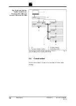
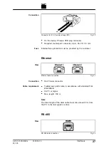
Connect system control (RS-485 connection) to the AC-DC mod-
ule (RS-485 SLAVE IN connection).
Connect the AC-DC module (RS-485 SLAVE OUT connection)
to the supplied terminating resistor.
A DC-DC module (RS-485 IN connection) is connected from the
AC-DC module (RS-485 MASTER connection).
If further DC-DC modules are operated, the RS-485 OUT con-
nection of the preceding DC-DC module is connected to the
RS-485 IN connection of the following DC-DC module.
Notes
■
The total length of the data cable from the system control to
the last DC-DC module via the AC-DC module must not
exceed 30 m.
■
If no further DC-DC module is connected to the DC-DC mod-
ule, the RS-485 OUT connection must be terminated with a
terminating resistor.
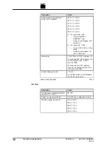
4.7
Interfaces on the system control
These interfaces are located on the system control TruConvert
System Control.
24 V supply voltage (DC)
Note
The negative terminal of the supply voltage is
not
connected to
PE in the TruConvert System Control. Grounding must be per-
formed by the customer, as close to the housing as possible.
24 V supply voltage (DC)
Fig. 19
26
Interfaces
2020-06-10
A67-0141-00.BKEN-
001-05
Use
Example
TruConvert System Control
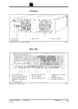
View
Содержание TruConvert AC 3025
Страница 1: ...Operator s manual TruConvert AC 3025 TruConvert System Control...
Страница 2: ......
Страница 6: ...II Good to know 2020 06 10 A67 0141 00 BKEN 001 05...


