BR3589
4.5 sec.
2.5
sec.
4.5 sec.
0.5 sec.
1.5 sec.
OFF
ON
Repeat
Start
One Cycle
0.5 sec.
P06329
SST
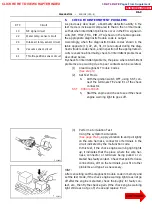
Check Connector
TE2
TE1
E1
S07193
--
DIAGNOSTICS
ENGINE (1RZ--E)
DI--5
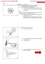
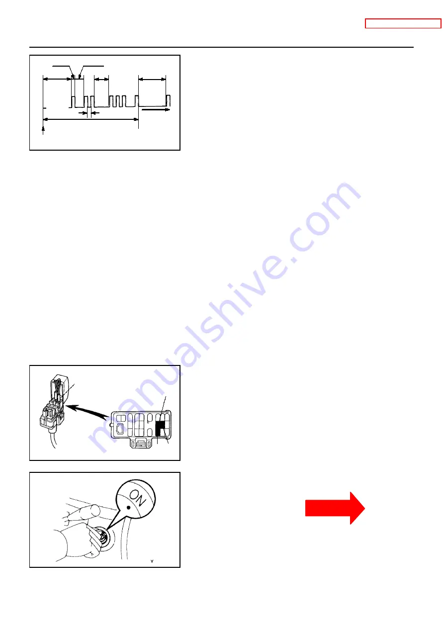
As an example, the blinking patterns for codes; nor-
mal, 12 and 31 are as shown on the illustration.
HINT:
If a diagnostic trouble code is not output, check the TE1 termi-
nal circuit
(4)
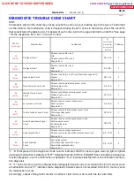
Check the details of the malfunction using the diag-
nostic trouble code chart on page
(5)
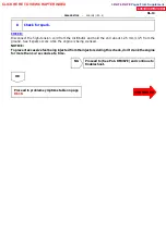
After completing the check, disconnect the SST
from terminals TE1 and E1, and turn off the display.
HINT:
If the event of 2 or more malfunction codes, indication will begin
from the smallest numbered code and continue in order to the
largest.
3. DIAGNOSIS INSPECTION (Test Mode)
HINT:
Compared to the normal mode, the test mode has an increased
sensing ability to detect malfunctions.
The same diagnostic items which are detected in the normal
mode can also be detected in the test mode.
(a)
Diagnostic Trouble Code Check
(1)
Initial conditions.
S
Battery positive voltage 11 V or more.
S
Throttle valve fully closed.
S
Air conditioning switched OFF.
(2)
Turn ignition switch OFF.
(3)
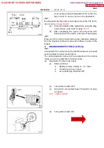
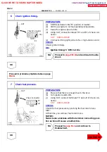
Using SST, connect terminals TE2 and E1 of check
connector.
(4)
Turn ignition switch ON.
CLICK HERE TO VIEW CHAPTER INDEX
Pages From Supplement
3RZ-F,3RZ-FE

