CO1206
Dimension ”B”
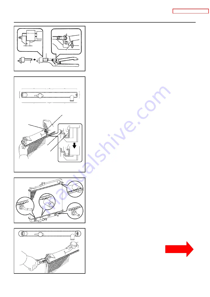
SST
Part ”A”
Stopper Bolt
Punch Assembly
Overhaul Handle
A01604
6
Stopper
Bolt
SST
Tank
Lock Plate
1
5
3
7
4
8
2
A01605
A01606
CO--16
--
COOLING
RADIATOR
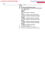
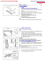
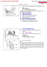
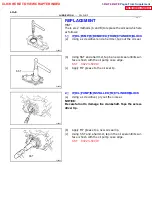
4. ASSEMBLE SST
SST 09230 -- 01010, 09231 -- 14010
(a)
Install the punch assembly to the overhaul handle, insert-
ing it in the hole in part ”A” as shown in the illustration.
(b)
While gripping the handle, adjust the stopper bolt so that
dimension ”B” shown in the diagram.
Dimension ”B”: 8.4 mm (0.34 in.)
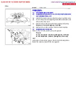
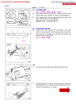
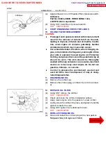
5 . CAULK LO CK P LATE
(a)
Lightly press SST against the lock plate in the order
shown in the illustration. After repeating this a few times,
fully caulk the lock plate by squeezing the handle until
stopped by the stopper bolt.
SST 09230 -- 01010
HINT:
S
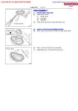
Do not stake the areas protruding around the ports.
S
The points shown in the rib sides near here cannot be
staked with SST. Use pliers or similar object and be care-
ful not to damage the core plates.
CLICK HERE TO VIEW CHAPTER INDEX
Pages From Supplement
3RZ-F,3RZ-FE

