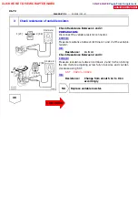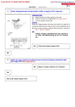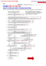
FI6588 FI6538
A00559
10 V/DIV.
GND
100 msec./Division (Idling)
Injection duration 1 msec./Division (Idling)
(Magnification)
10 V/DIV.
GND
A02467
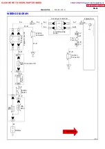
Engine ECU
25
12
13
26
E4
E4
E4
E4
L
L
L
R--L
R--L
R--L
BR
BR
No.2 Injector
No.1 Injector
No.4 Injector
No.3 Injector
B--R
B--R
B--R
B--R
B--R
IC6
9
B--R
J13
J14
A
C
B--R
Ignition Switch
W--R
2
2
30A
A
M
2
2
1
Battery
ED
W
6
7
#20
#10
E01
E02
Junction
Connector
Engine Room J/B
--
DIAGNOSTICS
ENGINE (1RZ--E)
DI--57
Injector Circuit
CIRCUIT DESCRIPTION
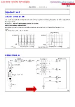
The injectors are situated in the intake manifold. They inject fuel into the cylinders based on the signals from
the engine ECU.
Reference: INSPECTION USING OSCILLOSCOPE
INJECTOR SIGNAL WAVEFORM
With the engine idling measure waveform between terminals #10, #20 and E01 of engine ECU.
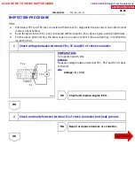
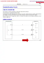
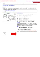
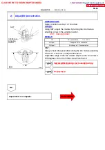
HINT:
The correct waveforms are as shown.
WIRING DIAGRAM
DI1I0--01
CLICK HERE TO VIEW CHAPTER INDEX
Pages From Supplement
3RZ-F,3RZ-FE

