Z17007
Fig. 4
Sensor C
A
1
2
1
2
1
2
ECU
B
5 V
5 V
0 V
5 V
Z17008
C
B
A
SHORT
Fig. 5
1
2
1
2
2
1
Z17009
Fig. 6
Sensor
ECU
C
B
A
1
2
1
2
1
2
IN--24
--
INTRODUCTION
HOW TO TROUBLESHOOT ECU CONTROLLED
SYSTEMS
(b)
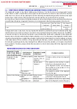
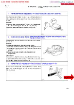
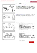
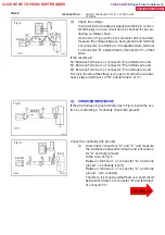
Check the voltage.
In a circuit in which voltage is applied (to the ECU connec-
tor terminal), an open circuit can be checked for by con-
ducting a voltage check.
As shown in Fig.4, with each connector still connected,
measure the voltage between body ground and terminal
1 of connector ”A” at the ECU 5V output terminal, terminal
1 of connector ”B”, and terminal 1 of connector ”C”, in that
order.
If the results are:
5V: Between Terminal 1 of connector ”A” and Body Ground
5V: Between Terminal 1 of connector ”B” and Body Ground
0V: Between Terminal 1 of connector ”C” and Body Ground
Then it is found out that there is an open circuit in the wire har-
ness between terminal 1 of ”B” and terminal 1 of ”C”.
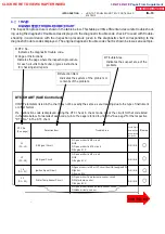
7 . CHE CK S HO RT CI RCUI T
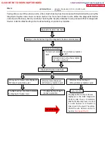
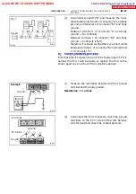
If the wire harness is ground shorted as in Fig.5, locate the sec-
tion by conducting a ”continuity check with ground”.
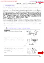
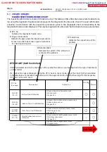
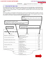
Check the continuity with ground.
(1)
Disconnect connectors ”A” and ”C” and measure
the resistance between terminal 1 and 2 of connec-
tor ”A” and body ground.
In the case of Fig.6
Between terminal 1 of connector ”A” and body
ground
→
Continuity (short)
Between terminal 2 of connector ”A” and body
ground
→
No continuity
Therefore, it is found out that there is a short circuit
between terminal 1 of connector ”A” and terminal 1
of connector ”C”.
CLICK HERE TO VIEW CHAPTER INDEX
Pages From Supplement
3RZ-F,3RZ-FE

