Z17808
Fig. 7
Sensor
ECU
C
A
1
2
1
2
1
2
2
1
B2
B1
IN0383
Example
Ground
IN0384
ECU Side
Ground
W/H Side
Ground
--
INTRODUCTION
HOW TO TROUBLESHOOT ECU CONTROLLED
SYSTEMS
IN--25
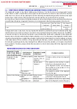
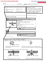
(2)
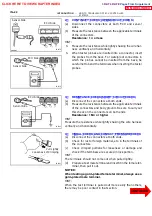
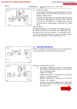
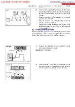
Disconnect connector ”B” and measure the resis-
tance between terminal 1 of connector ”A” and body
ground, and terminal 1 of connector ”B2” and body
ground.
Between terminal 1 of connector ”A” and body
ground
→
No continuity
Between terminal 1 of connector ”B2” and body
ground
→
Continuity (short)
therefore, it is found out that there is a short circuit
between terminal 1 of connector ”B2” and terminal
1 of connector ”C”.
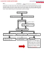
8 . CHE CK AND RE P L ACE E CU
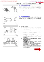
First check the ECU ground circuit. If it is faulty, repair it. If it is
normal, the ECU could be faulty, so replace the ECU with a
known good one and check if the symptoms appear.
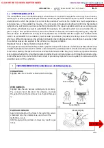
(1)
Measure the resistance between the ECU ground
terminal and the body ground.
Resistance: 1
Ω
or less
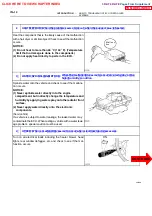
(2)
Disconnect the ECU connector, check the ground
terminals on the ECU side and the wire harness
side for bend and check the contact pressure.
CLICK HERE TO VIEW CHAPTER INDEX
Pages From Supplement
3RZ-F,3RZ-FE

