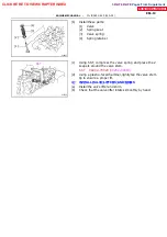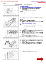
Z11078
(1)
(2)
(3)
P14910
Service Bolt
SST
Turn
P14672
Straight Pin
P14711
P15749
10
9
8
7
6
5
4
3
2
1
--
ENGINE MECHANICAL
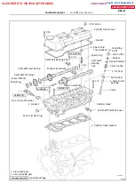
CYLINDER HEAD (2RZ--FE)
EM--55
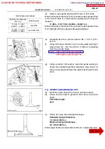
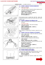
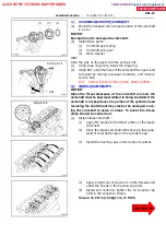
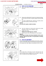
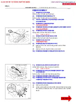
3. ASSEMBLE EXHAUS T CAMS HAFT
(a)
Mount the hexagon wrench head portion of the camshaft
in a vise.
NOTICE:
Be careful not to damage the camshaft.
(b)
Install these parts:
(1)
Camshaft gear spring
(2)
Camshaft sub--gear
(3)
Wave washer
HINT:
Align the pins on the gears with the spring ends.
(c)
Using snap ring pliers, install the snap ring.
(d)
Using SST, align the holes of the camshaft main gear and
sub--gear by turning sub--gear clockwise, and install a
service bolt.
SST 09960 -- 10010 (09962 -- 01000, 09963 -- 00500)
4 . I NS TALL CAMS HAFTS
NOTICE:
Since the thrust clearance of the camshaft is small, the
camshaft must be kept level while it is being installed. If the
camshaft is not kept level, the portion of the cylinder head
receiving the shaft thrust may crack or be damaged, caus-
ing the camshaft to seize or break. To avoid this, these
steps should be carried out.
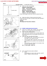
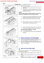
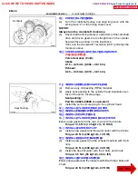
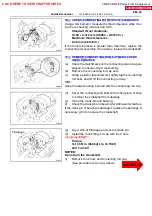
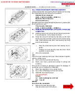
(a)
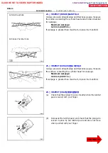
Install intake camshaft.
(1)
Apply MP grease to the thrust portion of the intake
camshaft.
(2)
Place the intake camshaft with knock pin facing up-
ward of camshaft angle on the cylinder head.
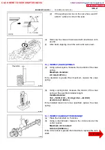
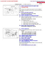
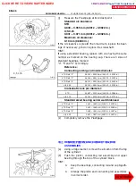
(3)
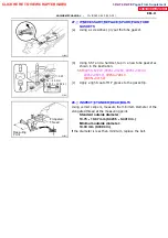
Install the bearing caps in their proper locations.
(4)
Apply a light coat of engine oil on the threads and
under the heads of the bearing cap bolts.
(5)
Install and uniformly tighten the 10 bearing cap
bolts in the sequence shown.
Torque: 15.5 N
∙
m (160 kgf
∙
cm, 12 ft
∙
lbf)
CLICK HERE TO VIEW CHAPTER INDEX
Pages From Supplement
3RZ-F,3RZ-FE

