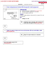
A00433
Combination
Meter
4--pulse
Engine ECU
Cable
T/M
A02283
G--O
9
E6
SPD
5V
E1
Engine ECU
C11
Combination Meter
1
--
DIAGNOSTICS
ENGINE (2RZ--FE, 3RZ--FE)
DI--143
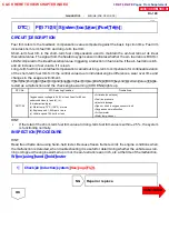
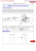
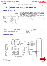
DTC P0500/42 Vehicle Speed Sensor Malfunction
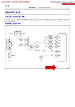
CIRCUIT DESCRIPTION
The vehicle speed sensor outputs a 4--pulse signal for every revolution of the rotor shaft, which is rotated
by the transmission output shaft via the driven gear. After this signal is converted into a more precise rectan-
gular waveform by the waveform shaping circuit inside the combination meter, it is then transmitted to the
engine ECU. The engine ECU determines the vehicle speed based on the frequency of these pulse signals.
DTC No.
DTC Detecting Condition
Trouble Area
S
Combination meter
P0500/42
No vehicle speed sensor signal to engine ECU during vehicle
S
Combination meter
S
Open or short in vehicle speed sensor circuit
P0500/42
No vehicle speed sensor signal to engine ECU during vehicle
driving
S
Open or short in vehicle speed sensor circuit
S
Engine ECU
driving
Engine ECU
S
Vehicle speed sensor
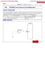
WIRING DIAGRAM
DI1IM--01
CLICK HERE TO VIEW CHAPTER INDEX
Pages From Supplement
3RZ-F,3RZ-FE

